文章编号: 2096-3203(2024)04-0253-09 中图分类号: TM771
我国10 kV中压配电网常采用消弧线圈接地方式[1-5],对于这种小电流接地方式,在线路发生单相接地故障时允许运行1~2 h,非故障相对地电压升高,在不同出线的绝缘薄弱处可能发生击穿并产生第二个接地点[6-9],形成同母两回线异相接地复故障。此外,受雷击、刮风等自然灾害的影响,容易发生同母两回线异相接地的情况[10]。同母两回线异相接地复故障发生时容易造成人畜触电事故,因此需要快速选出故障线路,防止危害扩大。
目前对于消弧线圈接地系统接地故障的研究主要针对单回线接地故障方面[11-15],单相故障检测技术与装置并不能很好地处理两点接地故障[16]。文献[17]针对配电网的相继接地故障,提出一种零序保护定值整定方法,但是该方法要依靠现场运行以及继电保护相关整定经验,没有经过严格的理论推导。文献[18]对消弧线圈接地系统同母多回线相继故障的发生机理进行研究,揭示了接地发生相间短路故障的原因,并提出一些抑制同母多回线相继故障发生的方法。文献[19]针对不接地系统偶发两出线相继接地故障处理难题,利用故障前后工频电气量信息,提出一种适用于不接地系统同名相两点接地故障的选线方法。文献[20]对多回线接地故障下的馈线零序电流关系进行推导,并提出一种自适应馈线零序电流保护方案,但是并不适用于异相接地的情形。文献[21]推导了小电阻接地系统中同母两回线金属性接地故障各馈线的零序电流,未考虑过渡电阻变化的情况。
文中在分析消弧线圈接地系统同母两回线异相接地复故障特征的基础上,提出一种基于零序导纳幅值比的故障选线方法。利用故障线路零序导纳幅值大于非故障线路零序导纳幅值的特征,选出所有的故障线路,最后经过PSCAD仿真表明,文中方法在故障位置、消弧线圈补偿度等因素的影响下仍能准确选出故障线路,具有较强的耐受过渡电阻的能力。
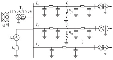
1 同母两回线异相接地复故障分析 1.1 故障点处电气量计算图 1为10 kV消弧线圈接地系统同母两回线异相接地故障示意。从母线出来总共有n条馈线,线路采用π型等值模型,在线路L1的f1点发生了B相接地故障,线路L2的f2点发生了C相接地故障。Rf1为第一个故障点f1处的过渡电阻;Rf2为第二个故障点f2处的过渡电阻;T0为接地变压器;T1为系统侧主变压器;Lp为消弧线圈。

|
图 1 10 kV消弧线圈接地系统 Fig. 1 10 kV resonant grounding system |
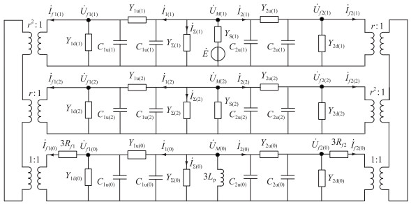
以A相为基准相,采用对称分量法,根据接地复故障边界条件,可得到同母两回线异相接地复故障的复合序网图如图 2所示,两侧为理想变压器,其变比的设计参考文献[22],文中所有变量的下标(1)、(2)、(0)均表示正、负、零序分量。

|
图 2 同母两回线两点异相接地复故障复合序网图 Fig. 2 Composite sequence network diagram of earth faults occurred in different phases of two feeders connected to the same bus |
图 2中,
根据同母两回线异相接地复故障的复合序网图,可建立如下的节点电压方程:
| $ \left\{ {\begin{array}{*{20}{l}} {{Y_{f1(1)}}{{\dot U}_{f1(1)}} - {Y_{1{\rm{u}}(1)}}{{\dot U}_{{\rm{M}}(1)}} = - r{{\dot I}_{f1(0)}}}\\ { - {Y_{{\rm{Iu}}(1)}}{{\dot U}_{f1(1)}} + {Y_{{\rm{M}}(1)}}{{\dot U}_{M(1)}} - {Y_{2{\rm{u}}(1)}}{{\dot U}_{f(1)}} = \dot E{Y_{{\rm{S}}(1)}}}\\ { - {Y_{2{\rm{u}}(1)}}{{\dot U}_{{\rm{M}}(1)}} + {Y_{f2(1)}}{{\dot U}_{f2(1)}} = - {r^2}{{\dot I}_{f2(0)}}}\\ {{Y_{f1(2)}}{{\dot U}_{f1(2)}} - {Y_{{\rm{lu}}(2)}}{{\dot U}_{{\rm{M}}(2)}} = - {r^2}{{\dot I}_{f1(0)}}}\\ { - {Y_{1{\rm{u}}(2)}}{{\dot U}_{f1(2)}} + {Y_{{\rm{M}}(2)}}{{\dot U}_{{\rm{M}}(2)}} - {Y_{2{\rm{u}}(2)}}{{\dot U}_{f2(2)}} = 0}\\ { - {Y_{2{\rm{u}}(2)}}{{\dot U}_{{\rm{M}}(2)}} + {Y_{f2(2)}}{{\dot U}_{f1(2)}} = - r{{\dot I}_{f2(0)}}}\\ {{Y_{f1(0)}}{{\dot U}_{f1(0)}} - {Y_{{\rm{lu}}(0)}}{{\dot U}_{{\rm{M}}(0)}} = - {{\dot I}_{f1(0)}}}\\ { - {Y_{1{\rm{u}}(0)}}{{\dot U}_{f1(0)}} + {Y_{{\rm{M}}(0)}}{{\dot U}_{{\rm{M}}(0)}} - {Y_{2{\rm{u}}(0)}}{{\dot U}_{f2(0)}} = 0}\\ { - {Y_{2{\rm{u}}(0)}}{{\dot U}_{{\rm{M}}(0)}} + {Y_{f2(0)}}{{\dot U}_{f1(0)}} = - {{\dot I}_{f2(0)}}} \end{array}} \right. $ | (1) |
式中: Yf1、Yf2分别为故障点f1、f2处的自导纳;YM为
理想变压器处的边界条件方程为:
| $ \left\{\begin{array}{l} r^2 \dot{U}_{f 1(1)}+r \dot{U}_{f 1(2)}+\dot{U}_{f 1(0)}=3 \dot{I}_{f 1(0)} R_{f 1} \\ r \dot{U}_{f 2(1)}+r^2 \dot{U}_{f 2(2)}+\dot{U}_{f 2(0)}=3 \dot{I}_{f 2(0)} R_{f 2} \end{array}\right. $ | (2) |
根据式(1)和式(2)可求解出2个故障点f1、f2处的正、负、零序电压,故障点处的零序电流以及母线处的正、负、零序电压,进而可以求解出各条线路首端的正、负、零序电流。
1.2 线路零序导纳计算采用零序分量进行分析,同母两回线的异相接地的零序网络如图 3所示,

|
图 3 同母两回线异相接地复故障零序网 Fig. 3 Zero sequence network of earth faults occurred in different phases of two feeders connected to the same bus |
结合零序网络结构,2条故障线路首端零序电流为:
| $ \dot{I}_{1(0)}=\left(\dot{U}_{\mathrm{M}(0)}-\dot{U}_{f 1(0)}\right) Y_{\mathrm{lu}(0)}+\frac{1}{2} \mathrm{j} \omega c_0 l_{f 1} \dot{U}_{\mathrm{M}(0)} $ | (3) |
| $ \dot{I}_{2(0)}=\left(\dot{U}_{\mathrm{M}(0)}-\dot{U}_{f 2(0)}\right) Y_{2 \mathrm{u}(0)}+\frac{1}{2} \mathrm{j} \omega c_0 l_{f 2} \dot{U}_{\mathrm{M}(0)} $ | (4) |
式中: ω为系统角频率;c0线路对地单位长度零序电容;lf1、lf2分别为故障点f1、f2到母线的距离。式(3)、式(4)中等式右边的第一部分为故障点上游线路导纳中流过的电流,第二部分为流向故障点上游对地电容的电流。
第i(i=3, 4, …, n)条非故障线路首端零序电流为:
| $ \dot{I}_{i(0)}=\dot{U}_{\mathrm{M}(0)} Y_{i(0)} $ | (5) |
式中: Yi(0)为第i条线路的总零序导纳。
利用线路首端的零序电流与母线零序电压比得到零序导纳,对于故障线路,其零序导纳计算见式(6)和式(7)。
| $ Y_{1(0)}=\frac{\dot{I}_{1(0)}}{\dot{U}_{\mathrm{M}(0)}}=\frac{1}{2} \mathrm{j} \omega c_0 l_{f 1}+\left(1-\frac{\dot{U}_{f 1(0)}}{\dot{U}_{\mathrm{M}(0)}}\right) Y_{1 \mathrm{u}(0)} $ | (6) |
| $ Y_{2(0)}=\frac{\dot{I}_{2(0)}}{\dot{U}_{\mathrm{M}(0)}}=\frac{1}{2} \mathrm{j} \omega c_0 l_{f 2}+\left(1-\frac{\dot{U}_{f 2(0)}}{\dot{U}_{\mathrm{M}(0)}}\right) Y_{2 \mathrm{u}(0)} $ | (7) |
对于第i条非故障线路,其零序导纳计算如式(8)所示。
| $ Y_{i(0)}=\frac{\dot{I}_{i(0)}}{\dot{U}_{\mathrm{M}(0)}}=\frac{4 \mathrm{j} \omega c_0 l_i-\omega^2 c_0^2 z_0 l_i^3}{2\left(2+\mathrm{j} \omega c_0 z_0 l_i^2\right)} \quad i=3, 4, \cdots, n $ | (8) |
式中: z0线路单位长度零序阻抗;li为第i条非故障线路长度。
1.3 零序导纳幅值特征分析为了得到各线路零序导纳之间的关系,用故障线路的零序导纳比上非故障路的零序导纳,根据式(6)—式(8)可得2条故障线路与第i条非故障线路的零序导纳比为:
| $ \begin{gathered} \frac{Y_{1(0)}}{Y_{i(0)}}=\left[\frac{1}{2} \mathrm{j} \omega c_0 l_{\mathrm{f} 1}+\left(1-\dot{U}_{\mathrm{f} 1 \mathrm{M}}\right) Y_{1 \mathrm{u}(0)}\right] / \\ \frac{4 \mathrm{j} \omega c_0 l_i-\omega^2 c_0^2 z_0 l_i^3}{2\left(2+\mathrm{j} \omega c_0 z_0 l_i^2\right)} \end{gathered} $ | (9) |
| $ \begin{gathered} \frac{Y_{2(0)}}{Y_{i(0)}}=\left[\frac{1}{2} \mathrm{j} \omega c_0 l_{\mathrm{f} 2}+\left(1-\dot{U}_{\mathrm{f} 2 \mathrm{M}}\right) Y_{2 \mathrm{u}(0)}\right] / \\ \frac{4 \mathrm{j} \omega c_0 l_i-\omega^2 c_0^2 z_0 l_i^3}{2\left(2+\mathrm{j} \omega c_0 z_0 l_i^2\right)} \end{gathered} $ | (10) |
式中:
| $ \dot{U}_{\mathrm{flM}}=\frac{a_1 R_{f 1}+a_2 R_{f 2}+a_3 / R_{f 2}+a_4}{b_1 R_{f 1}+b_2 R_{f 2}+b_3 / R_{f 1}+b_4 / R_{f 2}+b_5} $ | (11) |
式中: a1—a4和b1—b5均是只与2条线路的故障位置有关的参数,不包含与过渡电阻有关的量。
消弧线圈接地系统中,无论是架空线还是电缆,线路零序阻抗远小于对地容抗,因此在分析故障线路与非故障线路零序导纳之间的关系时,对于式(9)有:
| $ \left\{\begin{array}{l} \left|\frac{1}{2} \mathrm{j} \omega c_0 l_{f 1}\right| \ll\left|Y_{1 u(0)}\right|=\left|\frac{1}{z_0 l_{f 1}}\right| \\ \left|\omega^2 c_0^2 z_0 l_i^3\right| \ll\left|4 \mathrm{j} \omega c_0 l_i\right| \\ \left|\mathrm{j} \omega c_0 z_0 l_i^2\right| \ll 2 \end{array}\right. $ | (12) |
对式(9)取幅值,并忽略式(12)中幅值较小的量,可得到故障线路L1与第i条非故障线路的零序导纳幅值比Km1为:
| $ K_{\mathrm{m} 1}=\left|\frac{Y_{1(0)}}{Y_{i(0)}}\right|=\frac{\left|1-\dot{U}_{\mathrm{flM}}\right|\left|Y_{1 \mathrm{u}(0)}\right|}{\left|\mathrm{j} \omega c_0 l_i\right|} $ | (13) |
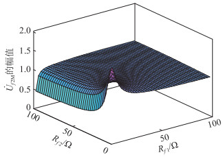
式(13)由
故障线路L2与故障线路L1的分析过程一致,故参照线路L1的分析过程同理可得故障线路L2与第i条非故障线路的零序导纳幅值比Km2为:
| $ K_{\mathrm{m} 2}=\left|\frac{Y_{2(0)}}{Y_{i(0)}}\right|=\frac{\left|1-\dot{U}_{\mathrm{f} 2 \mathrm{M}}\right|\left|Y_{2 \mathrm{u}(0)}\right|}{\left|\mathrm{j} \omega c_0 l_i\right|} $ | (14) |
对于
前面分析了故障线路与非故障线路之间的零序导纳特征,对于非故障线路,第j条故障线路的零序导纳与第i条故障线路的零序导纳比为:
| $ \begin{gathered} \frac{Y_{j(0)}}{Y_{i(0)}}=\frac{4 \mathrm{j} \omega c_0 l_j-\omega^2 c_0^2 z_0 l_j^3}{2+\mathrm{j} \omega c_0 z_0 l_j^2} / \frac{4 \mathrm{j} \omega c_0 l_i-\omega^2 c_0^2 z_0 l_i^3}{2+\mathrm{j} \omega c_0 z_0 l_i^2} \\ i \neq j \end{gathered} $ | (15) |
根据式(12)的关系,忽略对零序导纳幅值影响较小的量,非故障线路之间的零序导纳幅值比可表示为:
| $ K_{\mathrm{m} j}=\left|\frac{Y_{j(0)}}{Y_{i(0)}}\right|=\left|\frac{4 \mathrm{j} \omega c_0 l_j}{4 \mathrm{j} \omega c_0 l_i}\right|=\frac{l_j}{l_i} \quad i \neq j $ | (16) |
非故障线路零序导纳即为该条线路的总零序导纳,包括线路阻抗以及对地电容部分,在线路长度已知时其为一个固定量。由式(16)可以看出,非故障线路之间的零序导纳幅值比近似为线路的长度比,由于10 kV城市配电网的线路长度不超过20 km,故在一定的供电区域内,若线路长度相差不大,非故障线路之间的零序导纳幅值比很小。
2 同母两回线异相接地复故障选线原理 2.1 选线原理根据前面的分析,非故障线路之间的零序导纳差异较小,由式(13)可以看出,|Y1u(0)/(jωc0li)|部分由于线路零序阻抗与对地容的关系,存在|jωc0li|<<|Y1u(0)|,在2个过渡电阻处于某个范围内时,由于|Y1u(0)/(jωc0li)|的影响,Km1会达到很大值,远大于非故障线路之间的幅值比Kmj。对于Km2有同样的结论,即故障线路零序导纳幅值大于非故障线路零序导纳的幅值,可利用此特征进行故障选线。以线路首端零序电流最小的线路为参考线路,该线路的零序导纳在所有线路中最小,为非故障线路,用所有线路的零序导纳幅值比上参考线路的零序导纳幅值,可构造如下的选线判据:
| $ \begin{cases}K_{\mathrm{m} k}>K_{\text {set }} & \text { 故障线路 } \\ K_{\mathrm{m} k}<K_{2 \mathrm{set}} & \text { 非故障线路 }\end{cases} $ | (17) |
式中: Kmk为第k条线路与参考线路的零序导纳幅值比;K1set、K2set为设定值。
2.2 故障启动判据消弧线圈接地系统发生接地故障时会产生较大的零序电压,故障选线装置可以采用零序电压越限启动,当母线零序电压有效值超过设定的启动整定值Uset时,进行故障选线。因此启动判据可设为:
| $ U_{\mathrm{M}(0)}>U_{\text {set }} $ | (18) |
考虑到未发生故障时,由于三相不平衡也会出现零序电压,因此可按照躲开三相不平衡时出现的最大零序电压设定启动值,架空馈线的不平衡度一般不超过1.5%[23-26],可取零序电压整定值为相电压的10%,对于10 kV配电网,Uset=577 V。
2.3 参数整定对式(17)中的K1set、K2set进行整定,在式(13)、式(14)中,故障线路L1的故障点f1在线路末端时,|Y1u(0)/(jωc0li)|=1/(|z0lf1||jωc0li|)取最小值,根据《工业与民用配电设计手册》:“我国10 kV电压等级线路中,架空线的供电距离为6~20 km”[27-29],可令lf1=li=20 km,此时|Y1u(0)/(jωc0li)|达到最小,故障线路L2的情形亦是如此。对于|1-

|
图 4 |

|
图 5 |
基于零序导纳幅值比的故障选线方法流程如图 6所示。具体选线步骤如下:

|
图 6 故障选线方法流程 Fig. 6 Flow chart of fault line selection method |
(1) 判断母线电压是否满足选线启动判据,若满足则进行步骤(2), 否则继续监视线路状态。
(2) 获取各条线路首端零序电流与母线零序电压,利用线路首端零序电流与母线零序电压数据计算各条线路零序导纳。
(3) 以零序电流最小的线路作为参考线路,计算各条线路与参考线路的零序导纳幅值比。
(4) 判断各线路与参考线路的零序导纳幅值比是否大于K1set或小于K2set。若大于K1set则该线路为故障线路,若小于K2set则为非故障线路。
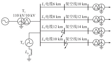
3 仿真验证在PSCAD平台搭建10 kV消弧线圈接地系统仿真模型,如图 7所示。系统采用架空-电缆混合线路,在母线出口处设有4条出线,具体线路的长度如图 7所示,系统采用过补偿10%,系统阻抗为(7.55×10⁻⁴+j0.360 7) Ω。架空线模型参考文献[25]中的架空线电气参数,具体参数如下。线路正序参数为:r1=0.17 Ω/km,x1=0.35 Ω/km,c1=0.12 μF/km。零序参数为:r0=0.32 Ω/km,x0=1.12 Ω/km,c0=6.4×10-3 μF/km。电缆线路正序参数为:r1=0.27 Ω/km,x1=0.08 Ω/km,c1=0.376 μF/km。零序参数为:r0=2.7 Ω/km,x0=0.35 Ω/km,c0=0.276 μF/km。假设线路L3发生B相接地故障,L4发生C相接地故障。

|
图 7 基于PSCAD的10 kV消弧线圈接地系统仿真模型 Fig. 7 Simulation model of 10 kV distribution network based on PSCAD |
为验证故障发生在线路不同位置时选线方法的准确性,在低阻Rf1=Rf2=10 Ω和高阻Rf1=Rf2=1 000 Ω时,设故障分别发生在线路首端、线路中间以及线路末端。根据仿真得到的结果,上述各种情况下零序电流最小的线路均为L1,故以此线为参考线路,用所有线路的零序导纳幅值比上该线路的零序导纳幅值,结合故障选线判据,最终得到的故障选线结果如表 1和表 2所示。
|
|
表 1 故障选线结果(Rf 1=Rf 2=10 Ω) Table 1 The results of fault line selection (Rf 1=Rf 2=10 Ω) |
|
|
表 2 故障选线结果(Rf 1=Rf 2=1 000 Ω) Table 2 The results of fault line selection (Rf 1=Rf 2=1 000 Ω) |
根据表 1和表 2选线结果可以看到,母线零序电压大于故障启动整定值,故障选线装置能够启动,而且无论故障发生在2条线路的哪个位置,故障线路与参考线路的零序导纳的幅值比大于非故障线路与参考线路的零序导纳幅值比,满足故障选线判据,都能够准确选出故障线路,故障选线结果不受故障位置的影响。
3.2 不同过渡电阻的仿真结果为验证在不同过渡电阻时故障选线方法的准确性,当故障发生在线路中间时,分别设置不同的过渡电阻进行仿真。根据仿真结果,各情形下零序电流最小的线路仍为L1,故以此线为参考线路,得到的选线结果如表 3所示。根据表 3结果,母线零序电压大于故障启动整定值,在不同过渡电阻影响下,故障线路与非故障线路的差异仍然明显,在1 000 Ω高阻时也可以判断出故障线路,具有一定的耐受过渡电阻能力。
|
|
表 3 不同过渡电阻时的故障选线结果 Table 3 The results of fault line selection under different fault resistances |
消弧线圈的补偿度对母线电压以及各线路零序电流都有影响,为验证在不同补偿状态下是否能选出故障线路,设线路L1发生B相接地故障,L4发生C相接地故障,故障发生在线路中间,过渡电阻Rf1=Rf2=100 Ω时,设置消弧线圈在过补偿、完全补偿以及欠补偿3种状态进行仿真验证,仿真得到各情形下零序电流最小的线路为L2,v为消弧线圈脱谐度,得到的选线结果如表 4所示。
|
|
表 4 不同消弧线圈补偿度下的故障选线结果 Table 4 The results of fault line selection under diffe-rent arcing suppression coil compensation degrees |
根据表 4结果,在消弧线圈处于不同的补偿状态时,选线装置均能够启动,故障选线结果准确,因此文中方法在消弧线圈处于不同运行状态下仍有很好的适应性。
3.4 母线出线数量的影响在实际电网中对于10 kV配电网存在10条以上的出线,为了验证母线出线数量对仿真结果的影响,在图 7母线中再引出一定数量的架空-电缆混合线路,多出的线路参数按照线路L2进行设置,则Km2的结果可反应其余线路的情况。对故障发生在线路中间,过度电阻均为20 Ω的情况进行仿真,得到的仿真结果如表 5所示。
|
|
表 5 不同出线数量的故障选线结果 Table 5 The results of fault line selection under different number of outgoing lines |
根据表 5结果可知,母线的出线数量对于故障选线的结果并无影响,故障线路与非故障线路的零序导纳幅值之间存在明显差异,在出线数量较多的情况下仍能选出故障线路。
4 结语文中通过对10 kV消弧线圈接地系统发生同母两回线异相接地复故障进行分析,发现故障线路零序导纳幅值比非故障线路的零序导纳幅值大得多,即使在1 000 Ω的高阻情况下也能达到非故障线路的2倍以上,进而提出基于零序导纳幅值比的故障选线方法。该方法利用线路首端的零序电流与母线零序电压之比得到零序导纳,通过各线路与参考线路的零序导纳幅值比选出故障线路,解决了同母两回线异相接地复故障难以选出所有故障线路的问题。PSCAD仿真结果表明,文中方法不受故障位置、消弧线圈补偿度的影响,能够耐受1 000 Ω过渡电阻,此外只需要单端信息,通信量小。
致谢
本文得到广州供电局有限公司科技项目(GZHKJXM20200081)资助,谨此致谢!
| [1] |
要焕年, 曹梅月. 电力系统谐振接地[M]. 2版. 北京: 中国电力出版社, 2009. YAO Huannian, CAO Meiyue. Power system resonant grounding[M]. 2nd ed.. Beijing: China Electric Power Press, 2009. (  0) 0) |
| [2] |
齐郑, 黄朝晖, 陈艳波. 基于零序分量的阻抗法配电网故障定位技术[J]. 电力系统保护与控制, 2023, 51(6): 54-62. QI Zheng, HUANG Zhaohui, CHEN Yanbo. Impedance fault location technology for a distribution network based on a zero-sequence component[J]. Power System Protection and Control, 2023, 51(6): 54-62. (  0) 0) |
| [3] |
喻锟, 邹豪, 曾祥君, 等. 谐振接地配电网对地绝缘参数双端谐振测量新方法[J]. 电力系统自动化, 2020, 44(12): 154-161. YU Kun, ZOU Hao, ZENG Xiangjun, et al. A novel double-terminal resonant measurement method of insulation-to-ground parameters for resonant grounding distribution network[J]. Automation of Electric Power Systems, 2020, 44(12): 154-161. (  0) 0) |
| [4] |
周斌, 陈梦琦, 郑海涯, 等. 谐振接地系统单相断线并坠地故障电压特征仿真分析[J]. 电力系统保护与控制, 2021, 49(17): 93-100. ZHOU Bin, CHEN Mengqi, ZHENG Haiya, et al. Simulation analysis of voltage characteristics of a single-phase line-broken and grounding fault in a resonant grounded system[J]. Power System Protection and Control, 2021, 49(17): 93-100. (  0) 0) |
| [5] |
陶维青, 李雪婷, 华玉婷, 等. 基于曼哈顿平均距离和余弦相似度的配网单相接地故障定位[J]. 电力工程技术, 2023, 42(2): 130-138. TAO Weiqing, LI Xueting, HUA Yuting, et al. Fault location of single-phase grounding fault based on Manhattan average distance and cosine similarity in distribution network[J]. Electric Power Engineering Technology, 2023, 42(2): 130-138. (  0) 0) |
| [6] |
刘映彤, 黄纯, 袁静泊, 等. 谐振接地系统两点同相接地故障暂态特征及选线[J]. 中国电力, 2022, 55(10): 62-70. LIU Yingtong, HUANG Chun, YUAN Jingbo, et al. Transientcharacteristics and line selection of two-point grounding faults on same phase in resonant grounding system[J]. Electric Power, 2022, 55(10): 62-70. (  0) 0) |
| [7] |
王苏, 曾铁军, 郑茂然. 中性点非有效接地电力系统异名相两点接地短路时的选择性跳闸决策[J]. 电网技术, 2010, 34(7): 195-199. WANG Su, ZENG Tiejun, ZHENG Maoran. Selective tripping strategy decision of two-point ground fault occurred in different phases of neutral non-effective grounding system[J]. Power System Technology, 2010, 34(7): 195-199. (  0) 0) |
| [8] |
楚恬歆, 张文海, 瞿科, 等. 基于复合判据的小电流接地系统接地型早期故障检测[J]. 高电压技术, 2022, 48(3): 1022-1031. CHU Tianxin, ZHANG Wenhai, QU Ke, et al. Grounded incipient fault detection based on compound criterion in non-solidly grounding system[J]. High Voltage Engineering, 2022, 48(3): 1022-1031. (  0) 0) |
| [9] |
汪明智. 中压配电网线路两点异相故障测距研究[D]. 重庆: 重庆大学, 2016. WANG Mingzhi. Study on location of arbitrary two points grounding faults in medium voltage distribution networks[D]. Chongqing: Chongqing University, 2016. (  0) 0) |
| [10] |
欧阳健娜, 俞小勇, 周杨珺, 等. 配网线路两点相继接地故障选线方法[J]. 南方电网技术, 2020, 14(6): 81-89. OUYANG Jianna, YU Xiaoyong, ZHOU Yangjun, et al. A fault line selection method for two-point successive grounding of power distribution lines[J]. Southern Power System Technology, 2020, 14(6): 81-89. (  0) 0) |
| [11] |
龙茹悦, 黄纯, 汤涛, 等. 一种谐振接地系统的配电线路接地故障选线新方法[J]. 电力系统保护与控制, 2019, 47(21): 21-29. LONG Ruyue, HUANG Chun, TANG Tao, et al. Line selection method for grounding fault in resonant grounding distribution systems[J]. Power System Protection and Control, 2019, 47(21): 21-29. (  0) 0) |
| [12] |
LI J, LIU Y L, LI C X, et al. An FTU-based method for locating single-phase high-impedance faults using transient zero-sequence admittance in resonant grounding systems[J]. IEEE Transactions on Power Delivery, 2022, 37(2): 913-922. DOI:10.1109/TPWRD.2021.3074217 (  0) 0) |
| [13] |
刘健, 陈曦子, 张志华, 等. 基于消弧线圈调制信号相关检测的高阻单相接地选线[J]. 电力系统保护与控制, 2023, 51(1): 63-70. LIU Jian, CHEN Xizi, ZHANG Zhihua, et al. High resistance single-phase grounding line selection in resonant grounding systems based on correlation detection[J]. Power System Protection and Control, 2023, 51(1): 63-70. (  0) 0) |
| [14] |
王尊贤, 武守远, 栾晓明. 基于虚拟能量变化率的谐振接地系统高阻接地故障选线方法[J]. 电力系统自动化, 2022, 46(3): 137-146. WANG Zunxian, WU Shouyuan, LUAN Xiaoming. Fault line selection method for high-impedance grounding fault of resonant grounded system based on change rate of virtual energy[J]. Automation of Electric Power Systems, 2022, 46(3): 137-146. (  0) 0) |
| [15] |
KRISHNATHEVAR R, NGU E E. Generalized impedance-based fault location for distribution systems[J]. IEEE Transactions on Power Delivery, 2012, 27(1): 449-451. DOI:10.1109/TPWRD.2011.2170773 (  0) 0) |
| [16] |
亓志滨, 田君杨, 薛永端, 等. 不接地系统异名相两点接地故障工频电气量及其对选线的影响分析[J]. 电工技术学报, 2023, 38(13): 3539-3551. QI Zhibin, TIAN Junyang, XUE Yongduan, et al. Analysis of power frequency electrical quantity and line selection applicability for two-point grounding faults occurring on different phases in isolated neutral system[J]. Transactions of China Electrotechnical Society, 2023, 38(13): 3539-3551. (  0) 0) |
| [17] |
江文东. 10 kV小电阻接地系统零序过流定值的探讨[J]. 电力自动化设备, 2002, 22(10): 73-75. JIANG Wendong. Discussion on zero sequence overcurrentsettings for 10 kV low resistance grounding system[J]. Electric Power Automation Equipment, 2002, 22(10): 73-75. (  0) 0) |
| [18] |
吴争荣, 蔡颖倩, 张俊潇, 等. 消弧线圈接地系统同母多回线相继故障分析[J]. 高电压技术, 2017, 43(7): 2402-2409. WU Zhengrong, CAI Yingqian, ZHANG Junxiao, et al. Fault analysis on successive fault of multi-feeders connected to the same bus in resonant grounding system[J]. High Voltage Engineering, 2017, 43(7): 2402-2409. (  0) 0) |
| [19] |
张宗熙, 薛永端, 董立明, 等. 不接地系统同名相两点接地故障工频特征及选线[J]. 电力系统及其自动化学报, 2022, 34(9): 9-16. ZHANG Zongxi, XUE Yongduan, DONG Liming, et al. Power frequency characteristics and line selection under two point grounding faults occurring in same phase in isolated neutral system[J]. Proceedings of the CSU-EPSA, 2022, 34(9): 9-16. (  0) 0) |
| [20] |
喻磊, 郭晓斌, 韩博文, 等. 小电阻接地系统馈线自适应零序电流保护原理及装置实现[J]. 电力自动化设备, 2017, 37(11): 125-131, 137. YU Lei, GUO Xiaobin, HAN Bowen, et al. Principle of adaptive zero-sequence current protection and implementation of its device for feeder of low resistance grounding system[J]. Electric Power Automation Equipment, 2017, 37(11): 125-131, 137. (  0) 0) |
| [21] |
曾德辉, 王钢, 李海锋, 等. 小电阻接地配电网多回线故障分析与自适应零序电流保护[J]. 电力自动化设备, 2019, 39(5): 45-52. ZENG Dehui, WANG Gang, LI Haifeng, et al. Fault analysis of multi-feeder grounding fault and self-adaptive zero-sequence current protection scheme for low-resistance grounding distribution network[J]. Electric Power Automation Equipment, 2019, 39(5): 45-52. (  0) 0) |
| [22] |
LI J, BI H R, LI C X, et al. Analysis and calculation method for multiple faults in low-resistance grounded systems with inverter-interfaced distributed generators based on a PQ control strategy[J]. International Journal of Electrical Power & Energy Systems, 2022, 138: 107980. (  0) 0) |
| [23] |
刘战磊, 曾祥君, 喻锟, 等. 基于不平衡过电压动态抑制的谐振接地配电网单相接地故障保护新方法[J]. 电力系统保护与控制, 2021, 49(8): 41-49. LIU Zhanlei, ZENG Xiangjun, YU Kun, et al. A new method of single-phase grounding fault protection for a resonant grounding distribution network based on unbalanced overvoltage dynamic suppression[J]. Power System Protection and Control, 2021, 49(8): 41-49. (  0) 0) |
| [24] |
丁敬明, 邹贵彬, 周成瀚, 等. 考虑参数不对称的配电网单相接地故障柔性消弧方法[J]. 电力系统保护与控制, 2023, 51(12): 58-67. DING Jingming, ZOU Guibin, ZHOU Chenghan, et al. A flexible arc suppression method for a single-phase grounding fault in a distribution network considering parameter asymmetry[J]. Power System Protection and Control, 2023, 51(12): 58-67. (  0) 0) |
| [25] |
刘丰, 曾祥君, 谢李为, 等. 基于相电压差值极性的配电网单相接地故障检测方法[J]. 电力系统保护与控制, 2023, 51(15): 155-165. LIU Feng, ZENG Xiangjun, XIE Liwei, et al. Single-phase grounding fault detection method for a distribution network based on phase voltage difference polarity value[J]. Power System Protection and Control, 2023, 51(15): 155-165. (  0) 0) |
| [26] |
孙震, 徐昊, 朱洪志, 等. 基于接地故障比的不平衡配电网单相接地故障选相方法[J]. 电力系统保护与控制, 2022, 50(12): 108-116. SUN Zhen, XU Hao, ZHU Hongzhi, et al. Phase selection method of single line to ground fault in unbalanced distribution network based on ground fault ratio[J]. Power System Protection and Control, 2022, 50(12): 108-116. (  0) 0) |
| [27] |
于洋, 范荣奇, 徐丙垠, 等. 小电流接地故障保护技术及其发展[J]. 供用电, 2023, 40(2): 1-8. YU Yang, FAN Rongqi, XU Bingyin, et al. Small current earth fault protection and its developments[J]. Distribution & Utilization, 2023, 40(2): 1-8. (  0) 0) |
| [28] |
张弛, 王淳, 潘建兵, 等. 谐振接地系统单相断线并电源侧接地故障电压特征分析[J]. 电网技术, 2022, 46(12): 4993-5005. ZHANG Chi, WANG Chun, PAN Jianbing, et al. Voltage characteristics analysis of single-phase disconnection with power resource side grounding fault in resonant earthed system[J]. Power System Technology, 2022, 46(12): 4993-5005. (  0) 0) |
| [29] |
刘健, 常小强, 张志华, 等. 基于零序电压的小电流接地系统高阻单相接地检测启动性能分析及其应用[J]. 供用电, 2023, 40(9): 27-35, 73. LIU Jian, CHANG Xiaoqiang, ZHANG Zhihua, et al. Analysis and applications of startup performance based on zero-sequence-voltage for single phase grounding fault detection of small current grounding systems[J]. Distribution & Utilization, 2023, 40(9): 27-35, 73. (  0) 0) |
| [30] |
李建蕊, 李永丽, 王伟康, 等. 基于零序电流与电压相位差变化的灵活接地系统故障选线方法[J]. 电网技术, 2021, 45(12): 4847-4855. LI Jianrui, LI Yongli, WANG Weikang, et al. Fault line detection method for flexible grounding system based on changes of phase difference between zero sequence current and voltage[J]. Power System Technology, 2021, 45(12): 4847-4855. (  0) 0) |
| [31] |
乔文, 师琛, 李舟, 等. 基于行波折反射特征和网络拓扑的配电网单相接地故障定位方法[J]. 供用电, 2022, 39(1): 65-73. QIAO Wen, SHI Chen, LI Zhou, et al. Single-phase ground fault location method of distribution network based on traveling wave refraction and reflection characteristics and network topology[J]. Distribution & Utilization, 2022, 39(1): 65-73. (  0) 0) |
 2024, Vol. 43


 韩捷(1983),男,硕士,高级工程师,从事配网设备全生命周期管理、配电网运行管理工作(E-mail: