文章编号: 2096-3203(2024)03-0226-08 中图分类号: TM34
直线感应电机(linear induction motor,LIM)由于初级的铁心开断而存在诸多干扰磁场,这些干扰磁场对电机的影响称为“边端效应”[1]。因此LIM的建模和控制过程须考虑实时变化的边端效应对励磁电感的影响。文献[2]对LIM励磁电感进行了研究,其成果在直线电机控制领域得到广泛应用,主要贡献为针对直线电机结构的特殊性引入无量纲系数Q,用Q的函数表示由边端效应导致的励磁电感的衰减规律。这种函数模型被称作Duncan模型,无须涉及大量参数,便于实时计算,从而被广泛应用。然而,文献[3]指出Duncan模型假设仅有恒定的初级励磁电流产生次级感应涡流,衰减系数的计算准确度不足,以六相LIM的励磁电感为研究对象,在Duncan模型的基础上进一步提升励磁电感变化规律的计算精度。
目前,LIM的驱动策略为基于速度闭环的矢量控制方法,具备优良的控制特性,但直线电机初级与次级的全程耦合路径中安装的速度传感器体积较大,且在强电磁环境下容易失效。因此,考虑电磁干扰的复杂环境以及对设备体积的苛刻要求,开展基于无速度传感器的LIM控制方法研究具有重要应用价值。
当前在感应电机控制领域,速度观测方法所基于的原理可分为信号注入法、电机理想模型和智能控制算法3类[4]。信号注入法会增大电机的推力波动[5],并增大电机的损耗[6];而智能控制算法对计算能力要求高,算法的计算速度难以跟上电机的控制周期,缺乏电机控制的实时性,因此最常用的是基于电机的理想模型法。基于电机理想模型的速度辨识方法有卡尔曼滤波法、模型参考自适应法和滑膜变结构控制法等[7]。模型参考自适应对估计模型的设计具有确定性方法,而卡尔曼滤波器在估计过程中具有随机方法,针对测量和初始扰动的噪声特性调整卡尔曼滤波器的能力突出了随机方法相对于确定性方法的优势[8-13]。
由于文中控制对象随着时间连续变化,因此将对电机系统进行离散化处理,再进行卡尔曼滤波,从而形成扩展卡尔曼滤波器[14-18]。目前,扩展卡尔曼滤波器对于转速的辨识已在三相旋转感应电机中得到初步应用[19-22]。这种方法抗干扰能力强[23-27]、鲁棒性高[28-33]、速度辨识准确度高。文中将运用扩展卡尔曼滤波算法,实现对LIM的速度观测和稳定性控制。
1 三相LIM数学模型文献[3]指出,六相LIM在坐标变换后的两相直角坐标系等效电路与三相LIM完全一致。因此,六相LIM励磁电感衰减系数的计算方式可以推广至三相LIM。文中采用文献[3]提出的计算精度更高的系数Ke来计算励磁电感,其计算方式如式(1)所示。
| $ \left\{\begin{array}{l} K_{\mathrm{e}}=\frac{1}{1+K_{\mathrm{m}}} \\ T_{\mathrm{r}}=\frac{L_{\mathrm{m}}+L_{\mathrm{r}}}{R_{\mathrm{r}}} \\ Q=\frac{D R_{\mathrm{r}}}{v\left(L_{\mathrm{m}}+L_{\mathrm{lr}}\right)} \\ \lambda=\sqrt{\left(\frac{R_{\mathrm{r}}}{2 L_{\mathrm{lr}}}\right)^2-\frac{R_{\mathrm{r}}}{L_{\mathrm{lr}} T_{\mathrm{r}}}} \\ S_1=-\frac{R_{\mathrm{r}}}{2 L_{\mathrm{lr}}}+\lambda \\ S_2=-\frac{R_{\mathrm{r}}}{2 L_{\mathrm{lr}}}-\lambda \\ K_{\mathrm{m}}=\frac{1}{Q}\left(1+\frac{S_2 \mathrm{e}^{S_1 T_{\mathrm{r}} Q}-S_1 \mathrm{e}^{S_2 T_{\mathrm{r}} Q}}{2 \lambda}\right) \end{array}\right. $ | (1) |
式中:Ke为励磁电感系数;Tr为次级时间常数;Lm为互感;Lr为次级电感;Llr为次级等效漏电感;Rr为次级等效电阻;Q为Duncan模型的无量纲系数;D为动子耦合部分长度;v为线速度;λ为感应涡流的系数;S1、S2为次级等效电容电压方程解的系数。
根据式(1)计算LIM的衰减变化励磁电感,以LIM的电流为状态变量,电压为输入变量,列出三相LIM的动态数学模型。其数学模型为αβ坐标系上的磁链电压方程式(2)、磁链电流方程式(3)和角频率方程式(4)组成的方程组。
| $ \left\{\begin{array}{l} \frac{\mathrm{d} \psi_{\mathrm{r} \alpha}}{\mathrm{d} t}= \\ \frac{L_{\mathrm{lr}}+L_{\mathrm{me}}}{L_{\mathrm{me}}}\left[U_{\mathrm{s} \alpha}-R_{\mathrm{s}} i_{\mathrm{s} \alpha}+\left(\frac{L_{\mathrm{me}}^2}{L_{\mathrm{lr}}+L_{\mathrm{me}}}-L_{\mathrm{ls}}-L_{\mathrm{me}}\right) \frac{\mathrm{d} i_{\mathrm{s} \alpha}}{\mathrm{d} t}\right] \\ \frac{\mathrm{d} \psi_{\mathrm{r} \beta}}{\mathrm{d} t}= \\ \frac{L_{\mathrm{lr}}+L_{\mathrm{me}}}{L_{\mathrm{me}}}\left[U_{\mathrm{s} \beta}-R_{\mathrm{s}} i_{\mathrm{s} \beta}+\left(\frac{L_{\mathrm{me}}^2}{L_{\mathrm{lr}}+L_{\mathrm{me}}}-L_{\mathrm{ls}}-L_{\mathrm{me}}\right) \frac{\mathrm{d} i_{s \beta}}{\mathrm{d} t}\right] \end{array}\right. $ | (2) |
| $ \left\{\begin{array}{l} \frac{\mathrm{d} \psi_{\mathrm{r} \alpha}}{\mathrm{d} t}=\frac{L_{\mathrm{me}} R_{\mathrm{r}}}{L_{\mathrm{lr}}+L_{\mathrm{me}}} i_{\mathrm{s} \alpha}-\frac{R_{\mathrm{r}}}{L_{\mathrm{lr}}+L_{\mathrm{me}}} \psi_{\mathrm{r} \alpha}-\omega_{\mathrm{r}} \psi_{\mathrm{r} \beta} \\ \frac{\mathrm{d} \psi_{\mathrm{r} \beta}}{\mathrm{d} t}=\frac{L_{\mathrm{me}} R_{\mathrm{r}}}{L_{\mathrm{lr}}+L_{\mathrm{me}}} i_{\mathrm{s} \beta}-\frac{R_{\mathrm{r}}}{L_{\mathrm{lr}}+L_{\mathrm{me}}} \psi_{\mathrm{r} \beta}+\omega_{\mathrm{r}} \psi_{\mathrm{r} \alpha} \end{array}\right. $ | (3) |
| $ \frac{\mathrm{d} \omega_{\mathrm{r}}}{\mathrm{d} t}=0 $ | (4) |
式中: ψrα、ψrβ分别为α、β轴次级磁链;t为时间;Lme为励磁电感,Lme=LmKe;Usα、Usβ分别为α、β轴初级电压;Rs为初级等效电阻;isα、isβ分别为α、β轴初级电流;Lls为初级等效漏电感;ωr为次级角频率。
2 扩展卡尔曼滤波观测器扩展卡尔曼滤波器算法是一种在线线性化的技术,按照估计轨道进行线性化处理,即泰勒展开,再进行线性的卡尔曼滤波。
若用k时刻的测量状态估计j时刻的状态,系统的过程噪声和测量噪声可近似为数学模型为零期望的高斯分布如式(5)和式(6)所示。
| $ \left\{\begin{array}{l} E\{w(k)\}=0 \\ \operatorname{Cov}(w(k), w(j))=\boldsymbol{Q}(k) \end{array}\right. $ | (5) |
式中:w(k)、w(j)分别为k、j时刻的过程噪声;E{w(k)}为过程噪声的期望;Q(k)为过程噪声的协方差矩阵。
| $ \left\{\begin{array}{l} E\{v(k)\}=0 \\ \operatorname{Cov}(v(k), v(j))=\boldsymbol{R}(k) \end{array}\right. $ | (6) |
式中:v(k)、v(j)分别为v、j时刻的测量噪声;E{v(k)}为测量噪声的期望;R(k)为测量噪声的协方差矩阵。
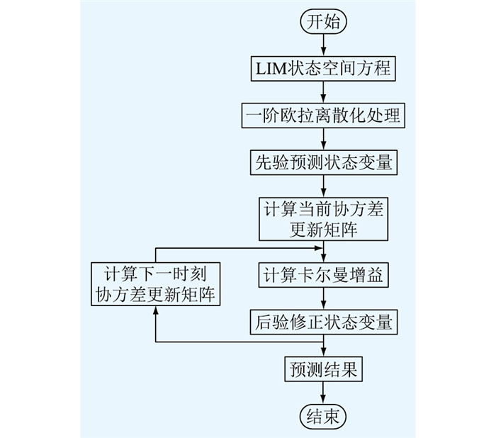
扩展卡尔曼滤波器的推导过程如图 1所示,电机系统离散化之后的卡尔曼滤波器推导可以分为以下5个步骤。
|
图 1 LIM扩展卡尔曼滤波器推导流程 Fig. 1 Derivation process of LIM extended Kalman filter |
步骤一:先验预测步,即根据k-1时刻的状态估计值来预测k时刻的状态估计值
步骤二:计算预测协方差更新矩阵Pk|k-1;
步骤三:计算卡尔曼增益Kk|k-1;
步骤四:后验修正,即通过卡尔曼增益计算得到状态变量的最优解
步骤五:计算下一时刻的协方差更新矩阵Pk|k。
(1) 先验预测。对三相LIM的数学模型式(2)、式(3)和式(4)组成的系统方程组进行离散化处理,得到线性的状态空间方程。
| $ \left\{\begin{array}{l} \hat{\boldsymbol{x}}_k=\hat{\boldsymbol{x}}_{k-1}+\left(\boldsymbol{A}_k \hat{\boldsymbol{x}}_{k-1}+\boldsymbol{B} \boldsymbol{u}_k\right) T_{\mathrm{s}}+\boldsymbol{w}_{k-1} \\ \boldsymbol{y}_k=\boldsymbol{H} \boldsymbol{x}_k+\boldsymbol{v}_k \end{array}\right. $ | (7) |
式中:
在LIM的状态空间方程式中,将矩阵元素的系数简化表达,取:
| $ \sigma=\frac{1}{L_{\mathrm{me}}^2 /\left(L_{\mathrm{lr}}+L_{\mathrm{me}}\right)-L_{\mathrm{ls}}-L_{\mathrm{me}}} $ | (8) |
| $ \tau=\frac{L_{\mathrm{me}}}{L_{\mathrm{lr}}+L_{\mathrm{me}}} $ | (9) |
则LIM的状态空间方程式的状态矩阵、输入矩阵和输出矩阵分别如式(10)—式(12)所示。
状态矩阵:
| $ \boldsymbol{A}_k=\left[\begin{array}{lllll} \boldsymbol{A}_1 & \boldsymbol{A}_2 & \boldsymbol{A}_3 & \boldsymbol{A}_4 & \boldsymbol{A}_5 \end{array}\right] $ | (10) |
其中:
| $ \left\{\begin{array}{l} \boldsymbol{A}_1=\left[\begin{array}{lllll} {\left[R_{\mathrm{s}}+\frac{L_{\mathrm{me}}^2 R_{\mathrm{r}}}{\left(L_{\mathrm{lr}}+L_{\mathrm{me}}\right)^2}\right] \sigma} & 0 & \frac{L_{\mathrm{me}} R_{\mathrm{r}}}{L_{\mathrm{lr}}+L_{\mathrm{me}}} & 0 & 0 \end{array}\right]^{\mathrm{T}} \\ \boldsymbol{A}_2=\left[\begin{array}{lllll} 0 & {\left[R_{\mathrm{s}}+\frac{L_{\mathrm{me}}^2 R_{\mathrm{r}}}{\left(L_{\mathrm{lr}}+L_{\mathrm{me}}\right)^2}\right] \sigma} & 0 & \frac{L_{\mathrm{me}} R_{\mathrm{r}}}{L_{\mathrm{lr}}+L_{\mathrm{me}}} & 0 \end{array}\right]^{\mathrm{T}} \\ \boldsymbol{A}_3= \\ \ \ \ \ \ \ {\left[\begin{array}{lllll} -\frac{L_{\mathrm{me}} R_{\mathrm{r}}}{\left(L_{\mathrm{lr}}+L_{\mathrm{me}}\right)^2} \sigma & \frac{L_{\mathrm{me}} \omega_{\mathrm{r}}}{L_{\mathrm{lr}}+L_{\mathrm{me}}} \sigma & -\frac{R_{\mathrm{r}}}{L_{\mathrm{lr}}+L_{\mathrm{me}}} & \omega_{\mathrm{r}} & 0 \end{array}\right]^{\mathrm{T}}} \\ \boldsymbol{A}_4= \\ \ \ \ \ \ \ {\left[\begin{array}{lllll} -\frac{L_{\mathrm{me}} \omega_{\mathrm{r}}}{L_{\mathrm{lr}}+L_{\mathrm{me}}} \sigma & -\frac{L_{\mathrm{me}} R_{\mathrm{r}}}{\left(L_{\mathrm{lr}}+L_{\mathrm{me}}\right)^2} \sigma & -\omega_{\mathrm{r}} & -\frac{R_{\mathrm{r}}}{L_{\mathrm{lr}}+L_{\mathrm{me}}} & 0 \end{array}\right]^{\mathrm{T}}} \\ \boldsymbol{A}_5=\left[\begin{array}{lllll} -\frac{L_{\mathrm{me}} \psi_{\mathrm{r} \beta}}{L_{\mathrm{lr}}+L_{\mathrm{me}}} \sigma & \frac{L_{\mathrm{me}} \psi_{\mathrm{r} \alpha}}{L_{\mathrm{lr}}+L_{\mathrm{me}}} \sigma & -\psi_{\mathrm{r} \beta} & \psi_{\mathrm{r} \alpha} & 0 \end{array}\right]^{\mathrm{T}} \end{array}\right. $ | (11) |
输入矩阵:
| $ \boldsymbol{B}=\left[\begin{array}{ccccc} -\sigma & 0 & 0 & 0 & 0 \\ 0 & -\sigma & 0 & 0 & 0 \end{array}\right]^{\mathrm{T}} $ | (12) |
输出矩阵:
| $ \boldsymbol{H}=\left[\begin{array}{lllll} 1 & 0 & 0 & 0 & 0 \\ 0 & 1 & 0 & 0 & 0 \end{array}\right] $ | (13) |
(2) 计算预测协方差更新矩阵。
| $ \boldsymbol{P}_{k \mid k-1}=\boldsymbol{F}_{k \mid k-1} \boldsymbol{P}_{k-1 \mid k-1} \boldsymbol{F}_{k \mid k-1}^{\mathrm{T}}+\boldsymbol{Q} $ | (14) |
过渡矩阵:
| $ \boldsymbol{F}=\boldsymbol{I}+T_{\mathrm{s}} \boldsymbol{A}_k=\left[\begin{array}{lllll} \boldsymbol{F}_1 & \boldsymbol{F}_2 & \boldsymbol{F}_3 & \boldsymbol{F}_4 & \boldsymbol{F}_5 \end{array}\right] $ | (15) |
式中:Fk|k-1为由k-1时刻得到的k时刻的过渡矩阵;I为单位矩阵;F1、F2、F3、F4和F5表达式如式(16)所示。
| $\left\{ \begin{array}{l}\begin{aligned} & \boldsymbol{F}_1=\left[\begin{array}{ll} 1+T_{\mathrm{s}}\left[R_{\mathrm{s}}+\frac{L_{\mathrm{me}}^2 R_{\mathrm{r}}}{\left(L_{\mathrm{lr}}+L_{\mathrm{me}}\right)^2}\right] \end{array} \begin{array}{llll} \sigma & 0 & \frac{L_{\mathrm{me}} R_{\mathrm{r}}}{L_{\mathrm{lr}}+L_{\mathrm{me}}} & 0& 0 \end{array}\right]^{\mathrm{T}} \\ & \boldsymbol{F}_2=\left[\begin{array}{ll} 0 & 1+T_{\mathrm{s}}\left[R_{\mathrm{s}}+\frac{L_{\mathrm{me}}^2 R_{\mathrm{r}}}{\left(L_{\mathrm{lr}}+L_{\mathrm{me}}\right)^2}\right] \end{array} \begin{array}{llll} \sigma & 0 & \frac{L_{\mathrm{me}} R_{\mathrm{r}}}{L_{\mathrm{lr}}+L_{\mathrm{me}}} & 0 \end{array}\right]^{\mathrm{T}} \\ & \boldsymbol{F}_3= \\ & {\left[\begin{array}{lllll} -\frac{L_{\mathrm{me}} R_{\mathrm{r}}}{\left(L_{\mathrm{lr}}+L_{\mathrm{me}}\right)^2} \sigma & \frac{L_{\mathrm{me}} \omega_{\mathrm{r}}}{L_{\mathrm{lr}}+L_{\mathrm{me}}} \sigma & 1-T_{\mathrm{s}} \frac{R_{\mathrm{r}}}{L_{\mathrm{lr}}+L_{\mathrm{me}}} & \omega_{\mathrm{r}} & 0 \end{array}\right]^{\mathrm{T}}} \\ & \boldsymbol{F}_4= \\ & {\left[\begin{array}{lllll} -\frac{L_{\mathrm{me}} \omega_{\mathrm{r}}}{L_{\mathrm{lr}}+L_{\mathrm{me}}} \sigma-\frac{L_{\mathrm{me}} R_{\mathrm{r}}}{\left(L_{\mathrm{lr}}+L_{\mathrm{me}}\right)^2} \sigma & -\omega_{\mathrm{r}} & 1-T_{\mathrm{s}} \frac{R_{\mathrm{r}}}{L_{\mathrm{lr}}+L_{\mathrm{me}}} & 0 \end{array}\right]^{\mathrm{T}}} \\ & \boldsymbol{F}_5=\left[\begin{array}{lllll} -\frac{L_{\mathrm{me}} \psi_{\mathrm{r} \beta}}{L_{\mathrm{lr}}+L_{\mathrm{me}}} \sigma & \frac{L_{\mathrm{me}} \psi_{\mathrm{r} \alpha}}{L_{\mathrm{lr}}+L_{\mathrm{me}}} \sigma & -\psi_{\mathrm{r} \beta} & \psi_{\mathrm{r} \alpha} & 1 \end{array}\right]^{\mathrm{T}} \\ & \end{aligned}\end{array} \right. $ | (16) |
(3) 计算卡尔曼增益。
| $ \boldsymbol{K}_{k \mid k-1}=\boldsymbol{P}_{k \mid k-1} \boldsymbol{H}^{\mathrm{T}}\left(\boldsymbol{H} \boldsymbol{P}_{k \mid k-1} \boldsymbol{H}^{\mathrm{T}}+\boldsymbol{R}\right)^{-1} $ | (17) |
(4) 后验修正。通过式(17)计算得到状态估计值的最优解为:
| $ \hat{\boldsymbol{x}}_{k \mid k}=\hat{\boldsymbol{x}}_{k \mid k-1}+\boldsymbol{K}_{k \mid k-1}\left(\boldsymbol{y}_k-\hat{\boldsymbol{y}}_{k \mid k-1}\right) $ | (18) |
(5) 计算下一时刻的协方差更新矩阵。下一时刻的协方差更新矩阵Pk|k的表达式为:
| $ \boldsymbol{P}_{k \mid k}=\left(\boldsymbol{I}-\boldsymbol{K}_{k \mid k-1} \boldsymbol{H}\right) \boldsymbol{P}_{k \mid k-1} $ | (19) |
扩展卡尔曼滤波器按照以上的求解步骤进行计算,不断求解更新下一时刻的协方差矩阵,最终使观测值逼近测量值。
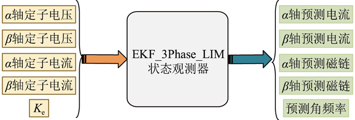
3 仿真实验 3.1 仿真系统在Simulink中搭建无速度传感器的LIM控制系统,利用卡尔曼滤波器观测速度,状态观测器模型如图 2所示,其中所采用的三相LIM参数如表 1所示。
|
图 2 卡尔曼滤波状态观测器仿真模块 Fig. 2 Simulation module of Kalman filter state observer |
|
|
表 1 三相LIM参数 Table 1 Parameters of the three-phase linear induction motor |
经过仿真试验,选取使仿真效果最佳的过程噪声、测量噪声和初始协方差矩阵参数如表 1所示。
过程噪声协方差矩阵 Q:
| $\boldsymbol{Q}=\operatorname{diag}\left(\begin{array}{lllll} 0.5 & 0.5 & 0.000\ 09 & 0.000\ 09 & 0.01 \end{array}\right) $ | (20) |
测量噪声协方差矩阵 R:
| $ \boldsymbol{R}=\operatorname{diag}\left(\begin{array}{ll} 0.005 & 0.005 \end{array}\right) $ | (21) |
初始协方差矩阵 P0:
| $ \boldsymbol{P}_0=\operatorname{diag}\left(\begin{array}{lllll} 1 & 1 & 1 & 1 & 1 \end{array}\right) $ | (22) |
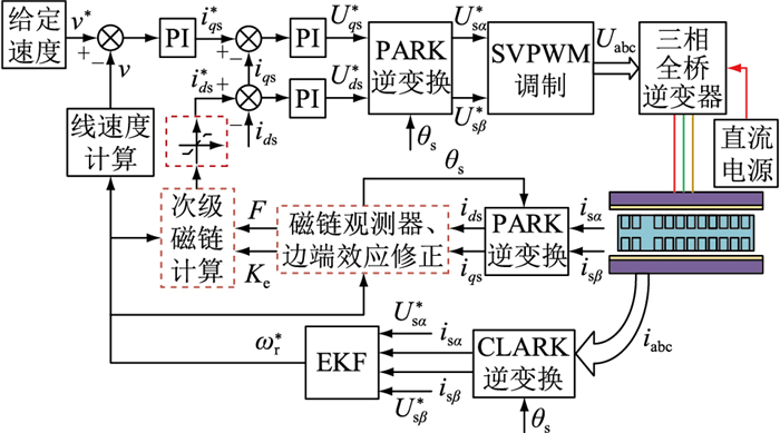
基于无速度传感器的三相感应电机矢量控制系统拓扑见图 3,采用空间矢量脉宽调制(space vector pulse width modulation, SVPWM)调制方式,控制策略采用比例积分(proportion integration, PI)控制,三相逆变器采用H桥结构,EKF为扩展卡尔曼滤波器。
|
图 3 三相感应电机的无速度传感器矢量控制系统拓扑 Fig. 3 Topology of three-phase induction motor vector control system without speed sensor |
图 3中,v*为线速度参考值;Usα*、Usβ*分别为α、β轴初级电压参考值;ωr*为次级角频率参考值;ids、ids*分别为定子侧d轴电流实际值和参考值;iqs、iqs*分别为定子侧q轴电流实际值和参考值;iabc为三相电流;Uds、Uds*分别为定子侧d轴实际电压和参考电压;Uqs、Uqs*分别为定子侧q轴实际电压和参考电压;Uabc为三相电压;θs为坐标变换用的角度;F为推力。
3.2 基于扩展卡尔曼滤波的LIM系统仿真分析为验证所推导的卡尔曼滤波器算法对LIM速度观测的效果,基于3.1节仿真拓扑结构,分别在空载工况、50%负载工况和额定负载工况下,对基于扩展卡尔曼滤波观测器的LIM控制系统动态性能进行分析,具体结果如下。
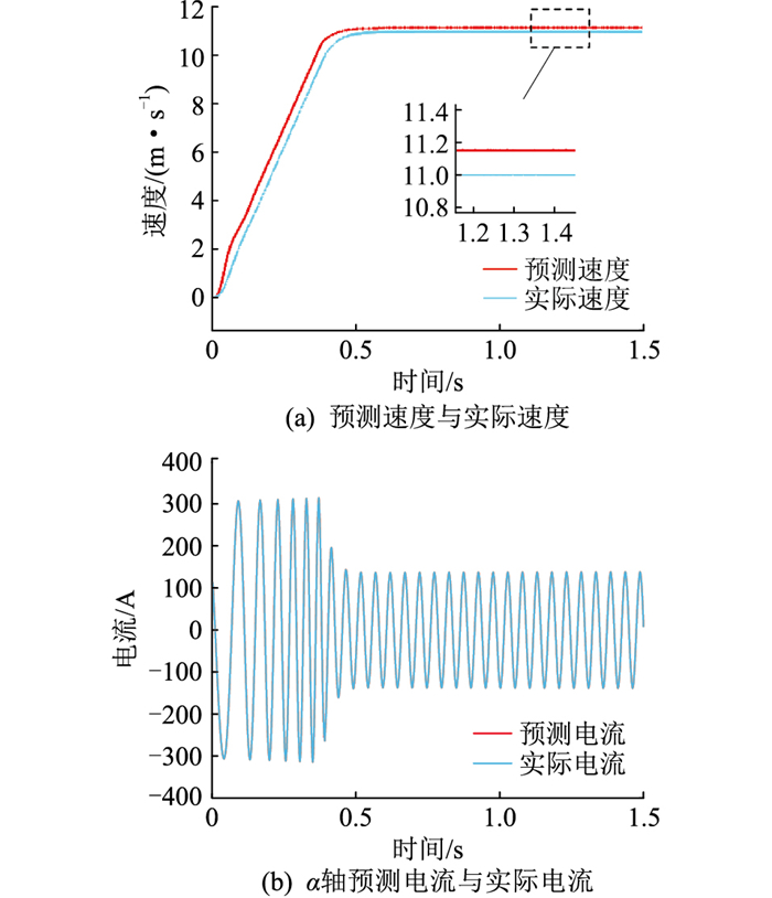
3.2.1 空载工况下系统动态性能分析如图 4所示,对空载工况下系统预测的速度、α轴电流和α轴磁链性能进行分析。图 4(a)表明系统进入稳态后,动子实际速度为11.10 m/s,预测速度为11.16 m/s,速度误差为0.06 m/s,约为0.54%,由此可知,预测速度可以满足跟踪实际速度的要求。α轴的预测电流和实际电流随时间变化的波形见图 4(b),可以看出预测值与实际值完全吻合。
|
图 4 基于扩展卡尔曼滤波观测器的系统动态性能(空载) Fig. 4 Dynamic performance of system based on extended Kalman filter observer (no-load) |
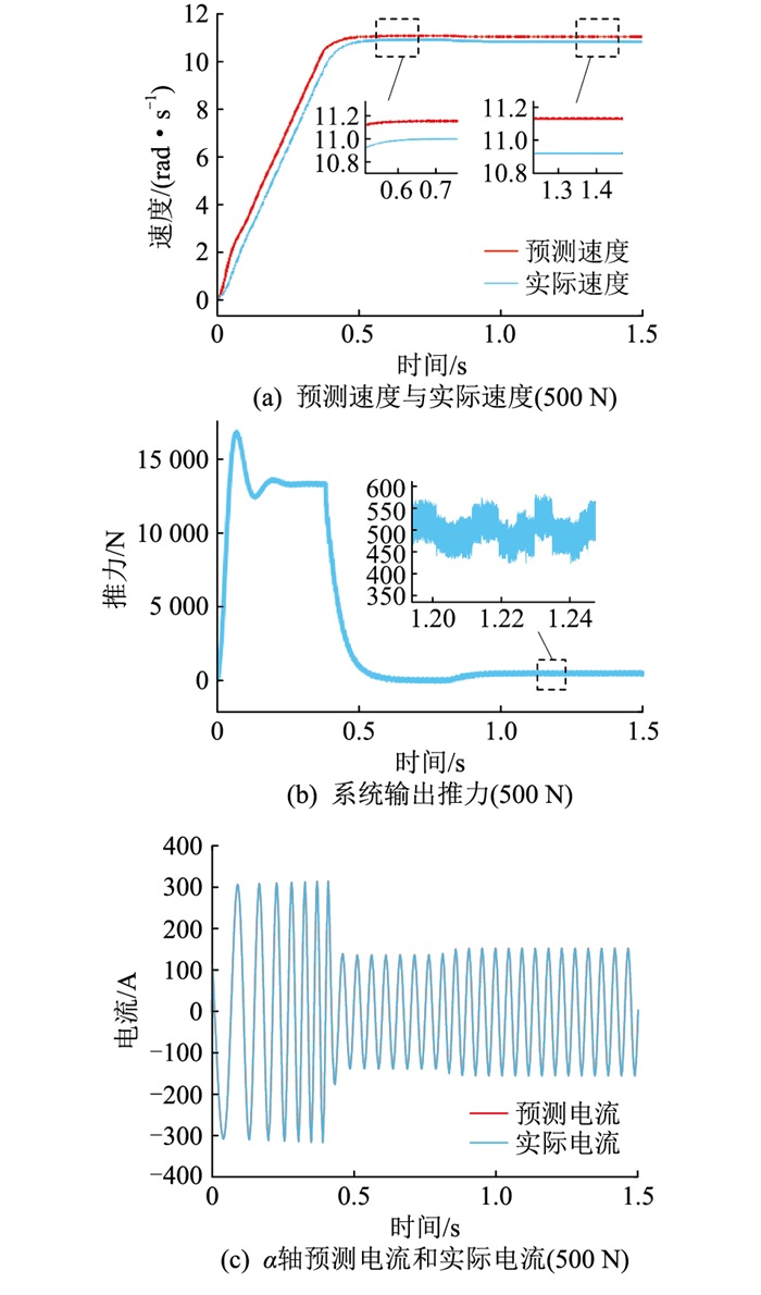
在空载系统能够稳定运行的基础上,在0.8 s时加入500 N的负载,采用卡尔曼滤波观测器的50%负载闭环控制系统运行结果如图 5所示。
|
图 5 基于扩展卡尔曼滤波观测器的系统动态性能(50%负载) Fig. 5 Dynamic performance of system based on extended Kalman filter observer (50% load) |
由图 5(a)可见,在加入50%负载之前系统的性能和空载时一致,加入500 N负载后,预测速度和实际速度的误差约为0.21 m/s。图 5(b)表明在暂态过程中,为了快速跟踪给定速度,电机输出的电磁推力远大于负载阻力,当系统加入负载后,电机输出推力的值基本稳定在目标值500 N左右,数值在410~600 N范围内波动。图 5(c)表明α轴的预测电流和实际电流随时间变化的波形依然完全吻合。
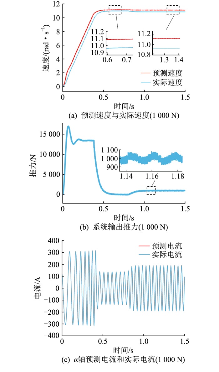
3.2.3 额定负载工况下系统动态性能分析第三组仿真是在0.8 s时加入1 000 N的负载。额定负载的控制系统的闭环效果如图 6所示。
|
图 6 基于扩展卡尔曼滤波观测器的系统动态性能(额定负载) Fig. 6 Dynamic performance of system based on extended Kalman filter observer (100% load) |
图 6 (a)表明,在额定负载工况下,预测速度和实际速度的误差约为0.26 m/s,可以看出,随着负载的加大,预测速度的误差也会相应地增大,但误差仍在可接受范围内。图 6 (b)为电机输出推力的波形,系统加入负载后,电机输出推力的值稳定在目标值1 000 N左右,数值在915~1 090 N范围内波动。图 6 (c)表明α轴的预测电流和实际电流随时间变化的波形仍然完全吻合。
3.2.4 3组不同负载工况下的系统性能对比3组不同负载工况下的系统动态性能如表 2所示。
|
|
表 2 动态性能分析 Table 2 Dynamic performance analysis |
由表 2可知,基于扩展卡尔曼滤波观测器的LIM矢量控制系统中,随着负载增大,预测速度的误差增大,推力误差减小。
形成误差的原因可能有以下2种:
(1) 扩展卡尔曼滤波法在给系统做离散化处理时,文中只离散到一阶导项,由于离散的阶次不够高,会导致观测器的输出量损失一部分精度。
(2) 由于卡尔曼滤波法中的噪声矩阵 Q、R一般由经验值或者试验值预估得到,无法使过程变量和测量变量完全一致[33]。
4 结论文中考虑LIM的动态边端效应,针对LIM取消速度传感器后,速度闭环反馈系统缺乏速度信息的问题进行了理论分析和公式推导,得到了卡尔曼滤波器的更新规律,并经过试验选取了最佳噪声参数,使得过程模型能模拟实际模型,实现了一种基于扩展卡尔曼滤波法的LIM速度观测器。
文中针对观测器的准确性和系统的稳定性进行了仿真验证,结果表明在3种负载情况下,观测器预测速度可以模拟实际速度,预测速度与实际速度之间的误差在0.51%~2.34%之间。对系统多种动态性能进行分析可知,由于对电机模型离散化的阶次不够高和噪声参数非理想化的原因,基于扩展卡尔曼滤波观测器的LIM矢量控制系统中,随着负载增大,预测速度的误差增大,推力误差减小,磁链幅值误差略微增大。
文中对电机系统离散化的阶次有限,导致预测模型不够理想化,且文中采用的LIM的励磁电感衰减系数的计算方式导致推力的纹波较大。下一步将重点研究如何进一步减小预测模型的误差,并减小励磁电感衰减系数对推力的波动影响。
| [1] |
叶云岳. 直线电机原理与应用[M]. 北京: 机械工业出版社, 2000: 40-52. YE Yunyue. Principle and application of linear motor[M]. Beijing: China Machine Press, 2000: 40-52. (  0) 0) |
| [2] |
DUNCAN J. Linear induction motor-equivalent-circuit model[J]. IEE Proceedings B: Electric Power Applications, 1983, 130(1): 51-57. DOI:10.1049/ip-b.1983.0008 (  0) 0) |
| [3] |
韩一, 聂子玲, 朱俊杰, 等. 考虑动态边端效应的六相直线感应电机数学模型及矢量控制[J]. 电机与控制学报, 2019, 23(3): 9-17. HAN Yi, NIE Ziling, ZHU Junjie, et al. Mathematical model and vector control of six-phase linear induction motor considering dynamic end effect[J]. Electric Machines and Control, 2019, 23(3): 9-17. (  0) 0) |
| [4] |
ZHANG Y P, YIN Z G, LIU J, et al. IPMSM sensorless control using high-frequency voltage injection method with random switching frequency for audible noise improvement[J]. IEEE Transactions on Industrial Electronics, 2020, 67(7): 6019-6030. DOI:10.1109/TIE.2019.2937042 (  0) 0) |
| [5] |
杨泽斌, 李方利, 陈正, 等. 基于低频信号注入法的无轴承异步电机转速自检测控制[J]. 农业工程学报, 2017, 33(2): 41-47. YANG Zebin, LI Fangli, CHEN Zheng, et al. Revolving speed self-detecting control based on low-frequency signal injection for bearingless induction motor[J]. Transactions of the Chinese Society of Agricultural Engineering, 2017, 33(2): 41-47. (  0) 0) |
| [6] |
CHEN C, LI L K, ZHANG Q, et al. Online inductor parameters identification by small-signal injection for sensorless predictive current controlled boost converter[J]. IEEE Transactions on Industrial Informatics, 2017, 13(4): 1554-1564. DOI:10.1109/TII.2016.2647079 (  0) 0) |
| [7] |
胡昊雨, 王聪, 刘瑞东, 等. 定子电流串联模型无速度传感器异步电机控制[J]. 计算机仿真, 2021, 38(4): 177-181. HU Haoyu, WANG Cong, LIU Ruidong, et al. Speed sensorless control of induction motor based on stator current series model[J]. Computer Simulation, 2021, 38(4): 177-181. DOI:10.3969/j.issn.1006-9348.2021.04.036 (  0) 0) |
| [8] |
尹华杰, 郭志宇, 曾君. 滑模无速度传感器感应电机的简化预测转矩控制[J]. 华南理工大学学报(自然科学版), 2020, 48(12): 18-26. YIN Huajie, GUO Zhiyu, ZENG Jun. Simplified predictive torque control for induction motor with sliding mode speed-sensorless[J]. Journal of South China University of Technology (Natural Science Edition), 2020, 48(12): 18-26. (  0) 0) |
| [9] |
ZHOU S L, LI G L, WANG Q J, et al. Rotor attitude estimation for spherical motors using multiobject Kalman KCF algorithm in monocular vision[J]. IEEE Transactions on Industrial Electronics, 2023, 70(1): 265-275. DOI:10.1109/TIE.2022.3148733 (  0) 0) |
| [10] |
张明, 陆东亮, 徐诗露, 等. 基于自适应容积卡尔曼滤波的动态谐波检测[J]. 智慧电力, 2022, 50(12): 48-54, 69. ZHANG Ming, LU Dongliang, XU Shilu, et al. Dynamic harmonic detection based on adaptive cubature Kalman filter[J]. Smart Power, 2022, 50(12): 48-54, 69. DOI:10.3969/j.issn.1673-7598.2022.12.009 (  0) 0) |
| [11] |
陈远, 黄林超, 刘丽斌, 等. 改进卡尔曼滤波及其在电力时钟同步系统中的应用[J]. 电力科学与技术学报, 2023, 38(2): 232-239. CHEN Yuan, HUANG Linchao, LIU Libin, et al. Improved Kalman filter and its application in power clock synchronization system[J]. Journal of Electric Power Science and Technology, 2023, 38(2): 232-239. (  0) 0) |
| [12] |
闵翔宇. 基于扩展卡尔曼滤波的永磁同步电机无速度传感器控制[D]. 株洲: 湖南工业大学, 2019. MIN Xiangyu. Speed sensorless control of permanent magnet synchronous motor based on extended Kalman filter[D]. Zhuzhou: Hunan University of Technology, 2019. (  0) 0) |
| [13] |
LU Q, WANG Y Q, MO L H, et al. Pulsating high frequency voltage injection strategy for sensorless permanent magnet synchronous motor drives[J]. IEEE Transactions on Applied Superconductivity, 2021, 31(8): 5204204. (  0) 0) |
| [14] |
孙兴法, 聂子玲, 朱俊杰, 等. 基于低阶串行双扩展卡尔曼滤波的永磁直线同步电机无速度传感器控制策略[J]. 电工技术学报, 2018, 33(12): 2685-2694. SUN Xingfa, NIE Ziling, ZHU Junjie, et al. A speed sensorless control strategy for a permanent magnet linear synchronous motor based on low-order serial dual extended Kalman filters[J]. Transactions of China Electrotechnical Society, 2018, 33(12): 2685-2694. (  0) 0) |
| [15] |
沈艳霞, 罗昌茜. 基于超螺旋滑模观测器的永磁同步直线电机无模型控制[J]. 电力系统保护与控制, 2023, 51(18): 62-69. SHEN Yanxia, LUO Changxi. Model-free control of a permanent magnet linear synchronous motor based on a super-twisting sliding mode observer[J]. Power System Protection and Control, 2023, 51(18): 62-69. (  0) 0) |
| [16] |
KUMAR R, DAS S. Model reference adaptive system-based sensorless speed control of grid-connected doubly fed induction generator in wind energy conversion system[J]. Iranian Journal of Science and Technology, Transactions of Electrical Engineering, 2020, 44(1): 129-140. DOI:10.1007/s40998-019-00196-5 (  0) 0) |
| [17] |
CAO R W, JIANG N, LU M H. Sensorless control of linear flux-switching permanent magnet motor based on extended Kalman filter[J]. IEEE Transactions on Industrial Electronics, 2020, 67(7): 5971-5979. DOI:10.1109/TIE.2019.2950865 (  0) 0) |
| [18] |
YILDIZ R, BARUT M, ZERDALI E. A comprehensive comparison of extended and unscented Kalman filters for speed-sensorless control applications of induction motors[J]. IEEE Transactions on Industrial Informatics, 2020, 16(10): 6423-6432. DOI:10.1109/TII.2020.2964876 (  0) 0) |
| [19] |
BOUNASLA N, BARKAT S, BENYOUSSEF E, et al. Sensorless sliding mode control of a five-phase PMSM using extended Kalman filter[C]//2016 8th International Conference on Modelling, Identification and Control (ICMIC). Algiers, Algeria. IEEE, 2016: 97-102.
(  0) 0) |
| [20] |
陈伟松. 基于卡尔曼滤波的感应电机无速度传感器控制[D]. 昆明: 昆明理工大学, 2016. CHEN Weisong. Speed sensorless control of induction motor based on Kalman filter[D]. Kunming: Kunming University of Science and Technology, 2016. (  0) 0) |
| [21] |
杨丹丹. 基于容积卡尔曼滤波异步电机无速度传感器矢量控制的研究[D]. 石家庄: 石家庄铁道大学, 2017. YANG Dandan. Research based on the cubature Kalman filter of speed sensorless vector control of asynchronous motor[D]. Shijiazhuang: Shijiazhuang Tiedao University, 2017. (  0) 0) |
| [22] |
田文丹. 基于扩展卡尔曼滤波器的交流异步电机转速和转子磁链观测器[D]. 北京: 北方工业大学, 2015. TIAN Wendan. Based on the extended Kalman filter of ac asynchronous motor speed and rotor flux observer[D]. Beijing: North China University of Technology, 2015. (  0) 0) |
| [23] |
QUANG N K, HIEU N T, HA Q P. FPGA-based sensorless PMSM speed control using reduced-order extended Kalman filters[J]. IEEE Transactions on Industrial Electronics, 2014, 61(12): 6574-6582. DOI:10.1109/TIE.2014.2320215 (  0) 0) |
| [24] |
王婷, 马继先, 瞿云飞, 等. 基于扩展卡尔曼滤波法的船舶永磁同步电机无传感器控制[J]. 软件, 2020, 41(7): 255-259. WANG Ting, MA Jixian, QU Yunfei, et al. Sensorless control of marine PMSM based on EKF[J]. Computer Engineering & Software, 2020, 41(7): 255-259. DOI:10.3969/j.issn.1003-6970.2020.07.053 (  0) 0) |
| [25] |
PASQUALOTTO D, RIGON S, ZIGLIOTTO M. Sensorless speed control of synchronous reluctance motor drives based on extended Kalman filter and neural magnetic model[J]. IEEE Transactions on Industrial Electronics, 2023, 70: 1321-1330. DOI:10.1109/TIE.2022.3159962 (  0) 0) |
| [26] |
NGUYEN T H, NGUYEN T T, NGUYEN V Q, et al. An adaptive sliding-mode controller with a modified reduced-order proportional integral observer for speed regulation of a permanent magnet synchronous motor[J]. IEEE Transactions on Industrial Electronics, 2022, 69(7): 7181-7191. DOI:10.1109/TIE.2021.3102427 (  0) 0) |
| [27] |
张海刚, 聂圆圆, 张磊, 等. 基于改进卡尔曼滤波的无速度传感器探究[J]. 系统仿真学报, 2018, 30(10): 3761-3769. ZHANG Haigang, NIE Yuanyuan, ZHANG Lei, et al. Research on sensorless control method based on improved Kalman filter of sliding mode observer[J]. Journal of System Simulation, 2018, 30(10): 3761-3769. (  0) 0) |
| [28] |
郑笑咏, 邓锦祥, 胡荏, 等. 无位置传感器无刷直流电机控制技术综述[J]. 电气传动, 2022, 52(24): 3-11, 66. ZHENG Xiaoyong, DENG Jinxiang, HU Ren, et al. Summary of control technology of position sensorless brushless DC motor[J]. Electric Drive, 2022, 52(24): 3-11, 66. (  0) 0) |
| [29] |
李宁. 小型船舶电力推进PMSM无位置传感器控制研究[D]. 淮南: 安徽理工大学, 2022. LI Ning. Research on sensorless control of PMSM for electric propulsion of small ships[D]. Huainan: Anhui University of Science & Technology, 2022. (  0) 0) |
| [30] |
郑诗程, 周甜军, 郎佳红. 基于扩展卡尔曼滤波的无速度传感器无刷双馈感应电机直接转矩控制[J]. 电源学报, 2022, 20(3): 126-132. ZHENG Shicheng, ZHOU Tianjun, LANG Jiahong. Speed sensorless direct torque control of brushless doubly-fed induction machine based on extended Kalman filter[J]. Journal of Power Supply, 2022, 20(3): 126-132. (  0) 0) |
| [31] |
许观达, 肖飞, 连传强, 等. 三相永磁同步电机单电流传感器矢量控制策略[J]. 电力系统保护与控制, 2022, 50(23): 104-111. XU Guanda, XIAO Fei, LIAN Chuanqiang, et al. A vector control strategy using a single current sensor for a three-phase permanentmagnet synchronous motor[J]. Power System Protection and Control, 2022, 50(23): 104-111. (  0) 0) |
| [32] |
王国庆, 杨春雨, 马磊, 等. 基于高斯-广义双曲混合分布的非线性卡尔曼滤波[J]. 自动化学报, 2023, 49(2): 448-460. WANG Guoqing, YANG Chunyu, MA Lei, et al. Nonlinear Kalman filter based on gaussian-generalized-hyperbolic mixing distribution[J]. Acta Automatica Sinica, 2023, 49(2): 448-460. (  0) 0) |
| [33] |
祁登亮, 冯静安, 倪向东等. 最大相关熵准则下改进扩展卡尔曼滤波的车辆状态估计[J/OL]. 机械科学与技术: 1-9[2023-02-20]. https://doi.org/10.13433/j.cnki.1003-8728.20220288. QI Dengliang, FENG Jingan, NI Xiangdong, et al. Vehicle state estimation with improved extended Kalman filter under maximum correntropy criterion[J/OL]. Mechanical Science and Technology for Aerospace Engineering: 1-9[2023-02-20]. https://doi.org/10.13433/j.cnki.1003-8728.20220288. (  0) 0) |
 2024, Vol. 43


 侯新国(1972),男,博士,副教授,研究方向为电力系统和装备故障诊断、信号检测与处理(E-mail: