文章编号: 2096-3203(2022)05-0202-08 中图分类号: TM341
2. 中国石油化工股份有限公司胜利油田分公司,山东 东营 257002;
3. 新南威尔士大学电气与通信学院,澳大利亚 悉尼 2052
变频软启动永磁同步电机依靠一台变频器实现多台电机的软启动[1—2],在变频驱动下切换到工频运行,对于不必调速的永磁同步电机,具有成本节约、操作简单方便等优点。与异步电机相比,永磁同步电机具有结构紧凑、功率因数高、功率密度大、可靠性高等优点[3—6],已被广泛应用于油田、矿井等工业领域[7—8],而网侧电压暂降易触发交流接触器等保护装置[9—10],使永磁同步电机退出运行进而引起生产过程中断,造成严重的经济损失。为此,油田现场常采取接触器延时跳闸等治理措施[11—12],保证永磁同步电机在暂降期间内不脱网。但目前对于永磁同步电机而言,这种治理措施具有较大的盲目性,因此有必要研究网侧发生电压暂降时永磁同步电机的低电压穿越能力评估方法,进而在线指导电压暂降治理措施的实施。
目前国内外针对电压暂降后电机低电压穿越能力评估方法的研究主要集中在异步电机,对永磁同步电机的研究相对较少。在异步电机方面,文献[13]提出一种在对称电压暂降下,基于稳态等效电路计算异步电机在特定暂降值下的电压暂降临界切除时间和绝对安全电压暂降的方法。文献[14—15]利用异步电机动态方程分析电机负荷特性对变频调速器电压暂降耐受特性的影响。文献[16]利用异步电机转差-电压-转矩关系分析电机在暂降前和暂降中的运动规律,推导出不同类型负载下的低电压穿越能力表达式。文献[17]建立转差率与负载转矩、端电压间的动态模型,分析电压短时中断后转动惯量等参数对异步电机低电压穿越能力的影响。在永磁同步电机方面,文献[18]分析电压波动对电机起动性能和稳态性能的影响,但未涉及电机暂态性能的研究。文献[19]分析电压暂降对变频调速永磁同步电机转速和定子电流变化的影响,但未考虑不受变频控制的永磁同步电机在电压暂降下的动态特性。文献[20]利用仿真研究电压暂降对异步启动永磁同步电机运行性能的影响,结果表明在暂降持续时间内会产生较大的定子电流和转矩峰值。综上所述,目前国内外尚未有针对变频软启动永磁同步电机低电压穿越能力评估方法的相关研究。
变频软启动永磁同步电机依靠变频器实现软启动后切换至工频运行,适用于起动困难但不必调速的电机,电压暂降易触发这类电机的保护装置动作而引发可能尚未失步的永磁同步电机被迫停机。因此,文中推导电压暂降暂态过程中的电磁转矩表达式,将转差率存在负值作为暂态稳定性判据,利用面积法则求出故障临界切除时间。研究永磁同步电机的低电压穿越能力评估方法可为电压暂降的治理提供一定的理论支撑。
1 永磁同步电机暂态力矩分析模型永磁同步电机作为一种多变量、非线性、强耦合的系统,为便于分析,一般不计饱和、剩磁、涡流、磁链损耗等影响,其数学模型[21—25]可以表示为:
| $ \left\{\begin{array}{l} u_d=R i_d+\frac{\mathrm{d} \psi_d}{\mathrm{~d} t}-\omega_{\mathrm{r}} \psi_q \\ u_q=R i_q+\frac{\mathrm{d} \psi_q}{\mathrm{~d} t}+\omega_{\mathrm{r}} \psi_d \end{array}\right. $ | (1) |
| $ \left\{\begin{array}{l} \psi_d=L_d i_d+\psi_{\mathrm{f}} \\ \psi_q=L_q i_q \end{array}\right. $ | (2) |
| $ T_{\mathrm{e}}=\psi_{\mathrm{f}} i_q+\left(L_d-L_q\right) i_d i_q $ | (3) |
式中:ud,uq分别为dq轴定子电压;R为定子电阻;ψd,ψq分别为dq轴定子磁链;id,iq分别为dq轴定子电流;ψf为永磁体磁链幅值;ωr为转子转速;Ld,Lq分别为dq轴电感;Te为电磁转矩。
文中以表贴式永磁同步电机为研究对象,电感可以简化为Ld=Lq=L。联立式(1)和式(2)可得定子dq轴电压为:
| $ \left\{\begin{array}{l} u_d=R i_d+L \frac{\mathrm{d} i_d}{\mathrm{~d} t}-\omega_{\mathrm{r}} L i_q \\ u_q=R i_q+L \frac{\mathrm{d} i_q}{\mathrm{~d} t}+\omega_{\mathrm{r}} L i_d+\omega_{\mathrm{r}} \psi_{\mathrm{f}} \end{array}\right. $ | (4) |
电压暂降后,电机由于电磁转矩与机械转矩的不平衡存在暂态过程,在此期间,定子dq轴电流是时变的,由式(3)可知,电磁转矩也随之变化,其功角曲线不再是稳态下的简单形式,要采用考虑定子绕组暂态的电磁转矩数学模型。
对式(4)进行拉普拉斯变换,求解频域下的q轴电流:
| $ \begin{gathered} I_q=\frac{(R+S L) U_q-\omega_{\mathrm{r}} L U_d+S\left(R L+S L^2\right) I_{q 0}}{S\left[(R+S L)^2+\left(\omega_{\mathrm{r}} L\right)^2\right]}- \\ \frac{(R+S L) \omega_{\mathrm{r}} \psi_{\mathrm{f}}+S \omega_{\mathrm{r}} L^2 I_{d 0}}{S\left[(R+S L)^2+\left(\omega_{\mathrm{r}} L\right)^2\right]} \end{gathered} $ | (5) |
式中:Id0,Iq0分别为暂降前dq轴的定子电流。
拉普拉斯反变换得到时域下的q轴电流:
| $ \begin{gathered} i_q=\frac{R u_q-\omega_{\mathrm{r}} L u_d-R \omega_{\mathrm{r}} \psi_{\mathrm{f}}}{R^2+\omega_{\mathrm{r}}^2 L^2}- \\ \frac{\mathrm{j} u_q-u_d+\mathrm{j} k_{\mathrm{a}} I_{q 0}-\mathrm{j} \omega_{\mathrm{r}} \psi_{\mathrm{f}}-k_{\mathrm{a}} I_{d 0}}{2 \omega_{\mathrm{r}} L+2 \mathrm{j} R} \mathrm{e}^{\frac{k_{\mathrm{a}} }{L}t}+ \\ \frac{-\mathrm{j} u_q-u_d-\mathrm{j} k_{\mathrm{b}} I_{q 0}+\mathrm{j} \omega_{\mathrm{r}} \psi_{\mathrm{f}}-k_{\mathrm{b}} I_{d 0}}{2 \mathrm{j} R-2 \omega_{\mathrm{r}} L} \mathrm{e}^{\frac{k_{\mathrm{b}}}{\mathrm{L}}t} \end{gathered} $ | (6) |
式中:ka=-R+jωrL;kb=-R-jωrL。
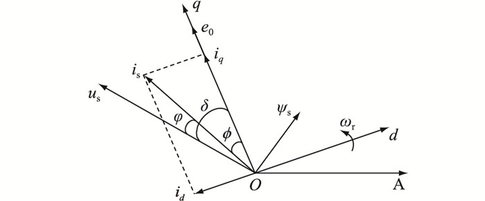
图 1为永磁同步电机在同步旋转坐标系下的空间矢量图,其中δ为功角;φ为功率因数角; ϕ为内功率因数角; us,is,ψs分别为电机定子电压、电流、磁链;e0为空载反电动势,e0=ωrψf;A为电机定子A相。

|
图 1 永磁同步电机矢量图 Fig. 1 Diagram of permanent magnet synchronous motor vectors |
由图 1永磁同步电机矢量图内的数学关系式可将q轴电流iq简化为:
| $ \begin{gathered} i_q=\frac{R u_{\mathrm{s}} \cos \delta+\omega_{\mathrm{r}} L u_{\mathrm{s}} \sin \delta-R \omega_{\mathrm{r}} \psi_{\mathrm{f}}}{R^2+\omega_{\mathrm{r}}^2 L^2}+ \\ \frac{\omega_{\mathrm{r}} L\left(u_{\mathrm{s}} \sin \left(\omega_{\mathrm{r}} t-\delta\right)-\omega_{\mathrm{r}} \psi_{\mathrm{f}} \sin \left(\omega_{\mathrm{r}} t\right)\right)}{R^2+\omega_{\mathrm{r}}^2 L^2} \mathrm{e}^{-\frac{R}{L}t}+ \\ \frac{R\left(\omega_{\mathrm{r}} \psi_{\mathrm{f}} \cos \left(\omega_{\mathrm{r}} t\right)-u_{\mathrm{s}} \cos \left(\omega_{\mathrm{r}} t-\delta\right)\right)}{R^2+\omega_{\mathrm{r}}^2 L^2} \mathrm{e}^{-\frac{R}{L} t}+ \\ I_{\mathrm{s} 0} \cos \left(\omega_{\mathrm{r}} t-\varphi_0\right) \mathrm{e}^{-\frac{R}{L} t} \end{gathered} $ | (7) |
式中:Is0,φ0分别为暂降前的定子电流和内功率因数角。
联立式(3)和式(7)可得永磁同步电机暂态过程中的电磁转矩Te为:
| $ \begin{gathered} T_{\mathrm{e}}=\psi_{\mathrm{f}} i_q=\\ \psi_{\mathrm{f}} \frac{R u_{\mathrm{s}} \cos \delta+\omega_{\mathrm{r}} L u_{\mathrm{s}} \sin \delta-R \omega_{\mathrm{r}} \psi_{\mathrm{f}}}{R^2+\omega_{\mathrm{r}}^2 L^2}+\\ \frac{\omega_{\mathrm{r}} \psi_{\mathrm{f}} L\left(u_{\mathrm{s}} \sin \left(\omega_{\mathrm{r}} t-\delta\right)-\omega_{\mathrm{r}} \psi_{\mathrm{f}} \sin \left(\omega_{\mathrm{r}} t\right)\right)}{R^2+\omega_{\mathrm{r}}^2 L^2} \mathrm{e}^{-\frac{R}{L} t}+\\ \frac{R \psi_{\mathrm{f}}\left(\omega_{\mathrm{r}} \psi_{\mathrm{f}} \cos \left(\omega_{\mathrm{r}} t\right)-u_{\mathrm{s}} \cos \left(\omega_{\mathrm{r}} t-\delta\right)\right)}{R^2+\omega_{\mathrm{r}}^2 L^2} \mathrm{e}^{-\frac{R}{L} t}+\\ \psi_{\mathrm{f}} I_{\mathrm{s} 0} \cos \left(\omega_{\mathrm{r}} t-\varphi_0\right) \mathrm{e}^{-\frac{R}{L} t} \end{gathered} $ | (8) |
由式(8)可知,永磁同步电机暂态过程中的电磁转矩与电压暂降幅值、暂降持续时间、转子转速和功角有关,且随时间变化。
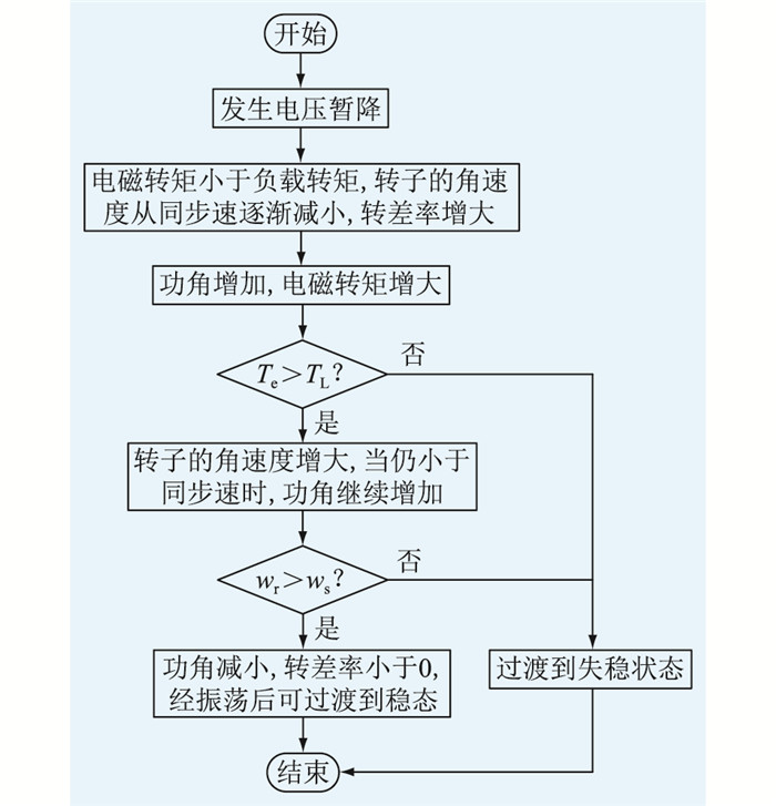
2 永磁同步电机低电压穿越能力评估方法 2.1 电机暂态稳定性分析判据及求解方法电路受扰动后从一个稳定状态到另一个稳定状态经历的过程为暂态过程。电压暂降后,永磁同步电机暂态演变过程如图 2所示。

|
图 2 电机暂态演变过程 Fig. 2 Motor transient evolution process |
由图 2可知,电压暂降后转子的角速度ωr从同步角速度ωs逐步下降(转差率s则从0逐步上升),功角δ和电磁转矩Te将逐步增大。当电磁转矩Te大于负载转矩TL时,ωr开始回升,在恢复到同步速时(s减小到0),δ将不再增大。由于Te>TL,故转子将继续加速,转子转速超过同步速(s < 0),此时δ将开始回摆并逐步减小,经过多次衰减振荡后可达到新的稳态运行点。
综上可知,电压暂降后电机能否恢复稳定的关键在于暂态过程中转子转速能否超过同步速,即转差率是否过负。由于转子转速不能突变,即转差率不能突变。因此,文中将转差率在暂降期间是否存在负值作为电机暂态是否稳定的判据。
永磁同步电机转子运动方程如式(9)所示。
| $ \left\{\begin{array}{l} J \frac{\mathrm{d} \omega_{\mathrm{r}}}{\mathrm{d} t}=T_{\mathrm{e}}-T_{\mathrm{L}} \\ s=\frac{\omega_{\mathrm{s}}-\omega_{\mathrm{r}}}{\omega_{\mathrm{s}}} \\ \delta=\left(\omega_{\mathrm{s}}-\omega_{\mathrm{r}}\right) t+\delta_0 \end{array}\right. $ | (9) |
式中:J为转动惯量;δ0为初始功角。
由式(8)和式(9)可知,永磁同步电机暂态运行时,电磁转矩、角转速和功角是随时间变化的,因此应采用数值法逐点进行求解,才能得到具体情况下的数值解。文中用转差率s替换转子角速度ωr,整理式(9)得:
| $ \left\{\begin{array}{l} \frac{\mathrm{d} \delta}{\mathrm{d} t}=\omega_{\mathrm{s}}-\omega_{\mathrm{r}}=\omega_{\mathrm{s}} s \\ \frac{\mathrm{d} s}{\mathrm{~d} t}=\frac{T_{\mathrm{L}}-T_{\mathrm{e}}}{J \omega_{\mathrm{s}}} \\ \delta=\frac{\mathrm{d} \delta}{\mathrm{d} t} \Delta t+\delta_0 \\ s=\frac{\mathrm{d} s}{\mathrm{~d} t} \Delta t+s_0 \end{array}\right. $ | (10) |
式中:s0为初始转差率。
采用龙格-库塔法求解数值解,实现动态过程分析,其递推公式为:
| $ \left\{\begin{array}{l} k_1=2 \pi f_{\mathrm{N}} s_{k-1} \\ k_1^{\prime}=\left(T_{\mathrm{L}}-T_{\mathrm{e}} \delta_{k-1}\right) /\left(J \omega_{\mathrm{s}}\right) \\ k_2=2 \pi f_{\mathrm{N}}\left(s_{k-1}+k_1^{\prime} \Delta t / 2\right) \\ k_2^{\prime}=\left[T_{\mathrm{L}}-T_{\mathrm{e}}\left(\delta_{k-1}+k_1 \Delta t / 2\right)\right] /\left(J \omega_{\mathrm{s}}\right) \\ k_3=2 \pi f_{\mathrm{N}}\left(s_{k-1}+k_2^{\prime} \Delta t / 2\right) \\ k_3^{\prime}=\left[T_{\mathrm{L}}-T_{\mathrm{e}}\left(\delta_{k-1}+k_2 \Delta t / 2\right)\right] /\left(J \omega_{\mathrm{s}}\right) \\ k_4=2 \pi f_{\mathrm{N}}\left(s_{k-1}+k_3^{\prime} \Delta t / 2\right) \\ k_4^{\prime}=\left[T_{\mathrm{L}}-T_{\mathrm{e}}\left(\delta_{k-1}+k_3 \Delta t / 2\right)\right] /\left(J \omega_{\mathrm{s}}\right) \end{array}\right. $ | (11) |
式中:fN为额定频率。联立式(10)和式(11)可求出迭代一次的功角δ和转差率s。
| $ \left\{\begin{array}{l} \delta_k=\delta_{k-1}+\left(k_1+2 k_2+2 k_3+k_4\right) \Delta t / 6 \\ s_k=s_{k-1}+\left(k_1^{\prime}+2 k_2^{\prime}+2 k_3^{\prime}+k_4^{\prime}\right) \Delta t / 6 \end{array}\right. $ | (12) |
经过迭代计算求出暂降期间功角和转差率随时间的变化数据,通过转差率是否存在负值判断该暂态下电机能否稳定。
2.2 故障临界切除时间确定方法根据2.1节永磁同步电机暂态稳定性判据,当转差率一直为正值时,表明电机在该暂降下运行一段时间后失稳。定义该暂降下,最长可运行时间为暂降临界切除时间,超过这个时间,即使电压恢复,电机也会失稳。暂降临界切除时间越长,电机低电压穿越能力越强。基于经典模型下的简单电力系统,利用面积法则求故障临界切除角度,见式(13)。
| $ \begin{gathered} \int_{\delta_0}^{\delta_{\mathrm{h}}}\left(P_{\mathrm{e}}-P_{\mathrm{L}}\right) \mathrm{d} \delta=\int_{\delta_0}^{\delta_{\mathrm{cr}}}\left(P_{\mathrm{e} 1}-P_{\mathrm{L}}\right) \mathrm{d} \delta+ \\ \int_{\delta_{\mathrm{cr}}}^{\delta_{\mathrm{h}}}\left(P_{\mathrm{e} 2}-P_{\mathrm{L}}\right) \mathrm{d} \delta=0 \end{gathered} $ | (13) |
式中:PL为恒功率负载;δcr为临界切除功角;δh为临界失稳功角;Pe1,Pe2分别为电压暂降期间和暂降后电磁功率。
电磁功率表达式Pe=Teωr结合式(8),整理得:
| $ \begin{gathered} P_{\mathrm{e}}=\frac{\frac{R \psi_{\mathrm{f}}}{\omega_{\mathrm{r}} L^2} u_{\mathrm{s}} \cos \delta+\frac{\psi_{\mathrm{f}}}{L} u_{\mathrm{s}} \sin \delta-\frac{R}{L^2} \psi_{\mathrm{f}}}{R^2 /\left(\omega_{\mathrm{r}}^2 L^2\right)+1}+\\ \frac{\frac{\psi_{\mathrm{f}}}{L}\left(u_{\mathrm{s}} \sin \left(\omega_{\mathrm{r}} t-\delta\right)-\omega_{\mathrm{r}} \psi_{\mathrm{f}} \sin \left(\omega_{\mathrm{r}} t\right)\right)}{R^2 /\left(\omega_{\mathrm{r}}^2 L^2\right)+1} \mathrm{e}^{-\frac{R}{L} t}+\\ \frac{R\left(\frac{\psi_{\mathrm{f}}^2}{L^2} \cos \left(\omega_{\mathrm{r}} t\right)-\frac{\psi_{\mathrm{f}} u_{\mathrm{s}}}{\omega_{\mathrm{r}} L^2} \cos \left(\omega_{\mathrm{r}} t-\delta\right)\right)}{R^2 /\left(\omega_{\mathrm{r}}^2 L^2\right)+1} \mathrm{e}^{-\frac{R}{L^t}}+\\ \omega_{\mathrm{r}} \psi_{\mathrm{f}} I_{\mathrm{s} 0} \cos \left(\omega_{\mathrm{r}} t-\varphi_0\right) \mathrm{e}^{-\frac{R}{L} t} \end{gathered} $ | (14) |
稳态情况下的dq轴定子电流为:
| $ \left\{\begin{array}{l} I_{q 0}=\left(U_{\mathrm{s} 0} \sin \delta_0\right) /\left(\omega_{\mathrm{r}} L\right) \\ I_{d 0}=\left(U_{\mathrm{s} 0} \cos \delta_0-\omega_{\mathrm{r}} \psi_{\mathrm{f}}\right) /\left(\omega_{\mathrm{r}} L\right) \end{array}\right. $ | (15) |
式中:Us0为暂降前定子电压。由于ωrL > > R,因此R/(ωrL)很小,可以忽略,联立式(14)和式(15)得:
| $ \begin{gathered} P_{\mathrm{e}}=\frac{\psi_{\mathrm{f}}}{L} u_{\mathrm{s}} \sin \delta+\left[\frac{\psi_{\mathrm{f}}}{L}\left(u_q-U_{q 0}\right) \sin \left(\omega_{\mathrm{r}} t\right)\right] \mathrm{e}^{-\frac{R}{L^t}}+ \\ {\left[\frac{\psi_{\mathrm{f}}}{L}\left(u_d-U_{d 0}\right) \cos \left(\omega_{\mathrm{r}} t\right)\right] \mathrm{e}^{-\frac{R}{L^t}}} \end{gathered} $ | (16) |
式中:Ud0,Uq0分别为暂降前dq轴的定子电压,将式(16)代入式(13)得:
| $ \begin{gathered} \int_{\delta_0}^{\delta_{\mathrm{h}}}\left(P_{\mathrm{e}}-P_{\mathrm{L}}\right) \mathrm{d} \delta= \\ \int_{\delta_0}^{\delta_{\mathrm{h}}}\left\{\frac{\psi_{\mathrm{f}}}{L} u_{\mathrm{s}} \sin \delta+\left[\frac{\psi_{\mathrm{f}}}{L}\left(u_q-U_{q 0}\right) \sin \left(\omega_{\mathrm{r}} t\right)\right] \mathrm{e}^{-\frac{R}{L} t}+\right. \\ \left.\left[\frac{\psi_{\mathrm{f}}}{L}\left(u_d-U_{d 0}\right) \cos \left(\omega_{\mathrm{r}} t\right)\right] \mathrm{e}^{-\frac{R}{L} t}-P_{\mathrm{L}}\right\} \mathrm{d} \delta \approx \\ \int_{\delta_0}^{\delta_{\mathrm{h}}}\left(\frac{\psi_{\mathrm{f}}}{L} u_{\mathrm{s}} \sin \delta-P_{\mathrm{L}}\right) \mathrm{d} \delta \end{gathered} $ | (17) |
式(15)积分中的周期性交变衰减分量关于横轴对称,因此可以忽略。假设已知临界功角δh,联立式(12)和式(16)可以求得电机的临界切除功角δcr,如式(18)所示。
| $ \delta_{\mathrm{cr}}=\arccos \left(\frac{u_{\mathrm{s} 2} \cos \delta_{\mathrm{h}}-u_{\mathrm{s} 1} \cos \delta_0+L P_{\mathrm{L}}\left(\delta_{\mathrm{h}}-\delta_0\right) / \psi_{\mathrm{f}}}{u_{\mathrm{s} 2}-u_{\mathrm{s} 1}}\right) $ | (18) |
式中:us1,us2分别为暂降期间和暂降后定子电压。
求出临界切除功角δcr后,利用龙格-库塔法求解临界切除功角对应的时间,即为临界切除时间tcr。将系统的实际切除时间tc和临界切除时间tcr相比较可以判断电机暂态是否失稳,将k=(tcr-tc)/tcr作为衡量电机稳定性的一种指标。当k>0时,电机稳定,k越大稳定程度越高;k < 0时,电机失稳。
3 仿真分析与验证为验证模型的准确性及评估方法的可行性,基于龙格-库塔法数值积分法与PSCAD建模仿真进行对比分析,其中理论计算是基于理想电机数学模型所构建的暂态力矩分析模型,仿真数据是基于更贴近现场实际的永磁同步电机模型。由于PSCAD自带模型转子上有2个用于异步起动的阻尼绕组,而文中不考虑电机起动问题,且阻尼绕组在正常运行时不起作用,在转速刚降低时对电磁转矩造成的影响较小,故仿真时忽略其影响,电机参数见表 1。
|
|
表 1 永磁同步电机参数 Table 1 Permanent magnet synchronous motor parameters |
文中研究的永磁同步电机位于配网端,而引发配网侧电压暂降的因素主要有短路故障、变压器投运和大容量感应电机起动等,短路故障是最主要的电压暂降成因,以三相短路故障最为严重。因此,以三相短路故障造成的电压暂降进行仿真分析。
3.1 电机暂态力矩模型仿真验证设置永磁同步电机正常工作时机端线电压有效值为380 V,电压暂降发生时刻为5 s。三相短路后,受过渡电阻以及距离故障点远近的影响,不同位置的电机遭受的电压暂降程度不同。电压暂降幅值U为0.8 p.u.,0.7 p.u.,0.6 p.u.情况下,永磁同步电机理论计算和PSCAD仿真对比如图 3所示。

|
图 3 不同电压暂降幅值下的角速度-时间曲线 Fig. 3 Angular velocity-time curves under different voltage sag amplitudes |
由图 3可知,理论计算与建模仿真得到的角速度曲线接近一致,验证了永磁同步电机暂态力矩分析模型理论推导的准确性。
3.2 电机暂态稳定性判据仿真验证由3.1节可知,该永磁同步电机的临界失稳电压为0.6~0.7 p.u.,文中以0.01 p.u.作为步长在此电压暂降范围内进行理论计算,与仿真形成的角速度对比以及理论计算得到的转差率见图 4—图 6。

|
图 4 当U=0.61 p.u.时角速度与转差率曲线 Fig. 4 Angular velocity-time curve and slip-time curve at U=0.61 p.u. |

|
图 5 当U=0.62 p.u.时角速度与转差率曲线 Fig. 5 Angular velocity-time curve and slip-time curve at U=0.62 p.u. |

|
图 6 当U=0.63 p.u.时角速度与转差率曲线 Fig. 6 Angular velocity-time curve and slip-time curve at U=0.63 p.u. |
由图 4—图 6可知,当转差率过负时,电机在该暂降下能够恢复稳定;当转差率一直大于0时,电机会失稳。验证了将永磁同步电机的转差率在暂降期间存在负值作为电机暂态期间能够恢复稳定的判据的准确性。
3.3 电机带载率对安全稳定临界电压的影响基于转差率的电机暂态稳定分析判据可确定永磁同步电机的安全稳定临界电压。改变永磁同步电机带载率,将数值积分法求得的转差率临界负值对应的电压作为该带载率下永磁同步电机的安全稳定临界电压。在PSCAD模型中,设置永磁同步电机端电压的暂降幅值从0开始以0.01 p.u.递增,将能够恢复稳定的暂降电压作为安全稳定临界电压,2种仿真结果对比见表 2,曲线见图 7。
|
|
表 2 理论与仿真得到的安全稳定临界电压对比 Table 2 Comparison of safety and stability critical voltage obtained by theory and simulation |

|
图 7 理论与仿真得到的安全稳定临界电压对比曲线 Fig. 7 Comparison curve of safety and stability critical voltage obtained by theory and simulation |
由表 2可知,理论计算与仿真得到的暂态稳定临界电压相对误差均小于6%,表明将转差率是否存在负值作为电机能否稳定的判据,进而确定暂态稳定临界电压是可行的,且电机带载率越高,暂态稳定临界电压幅值越高。
3.4 电压暂降幅值对故障临界切除时间的影响为简化分析,将δh=180°设定为临界功角,在电机满载情况下改变电压暂降幅值,利用式(18)求解故障临界切除功角,进行数值解计算得到理论切除时间,与仿真结果对比见表 3,得到的曲线见图 8。
|
|
表 3 不同电压暂降下故障临界切除时间对比 Table 3 Comparison of critical fault removal time for different voltage sags |

|
图 8 不同电压暂降下理论与仿真临界时间对比 Fig. 8 Comparison of theoretical and simulation critical time for different voltage sags |
由表 3可知,理论计算与仿真结果的相对误差在某些暂降情况下为0,而在其他暂降情况下处于4.76%~8.10%,表明相对误差具有一定的波动性,这种现象与龙格-库塔法计算步长的选择有关,步长选择不当容易引起数值计算不稳。文中的计算步长为0.001~0.05 s,选择0.01 s是为在数值计算收敛的前提下与PSCAD仿真模型的采样步长保持一致,PSCAD仿真模型中采样步长太小波形容易波动,太大容易失稳。文中仿真误差在合理范围内,验证了故障临界切除时间方法的有效性。由图 8可知,电机的故障临界切除时间与电压暂降幅值有关,电压暂降幅值越大,故障临界切除时间越长。
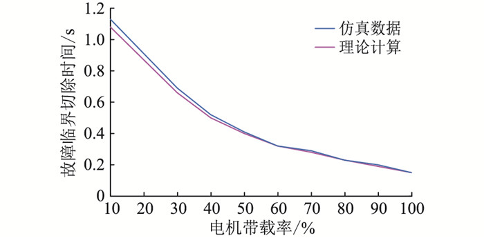
3.5 电机带载率对故障临界切除时间的影响设定电压暂降幅值为0.1 p.u.,仿真电机带载率对故障临界切除时间的影响,仿真数据如表 4所示,曲线如图 9所示。
|
|
表 4 不同电机带载率下故障临界切除时间对比 Table 4 Comparison of critical fault removal time for different motor load rates |

|
图 9 不同电机带载率下理论与仿真临界时间对比 Fig. 9 Comparison of theoretical and simulation critical time for different motor load rates |
仿真结果表明,电机的故障临界切除时间与电机带载率有关,且电机带载率越低,故障临界切除时间越长。
4 总结变频软启动永磁同步电机在工频运行时不受变频器控制,分析其低电压穿越能力时可忽略变频器的影响。文中基于dq同步旋转坐标系构建永磁同步电机暂态力矩分析模型,提出电机低电压穿越能力评估方法,对比Matlab理论计算与PSACD仿真结果验证永磁同步电机低电压穿越能力评估方法的可行性,研究结果表明:
(1) 网侧电压暂降场景下的永磁同步电机转差率是否存在负值可以作为电机暂态能否稳定的判据,通过暂态稳定判据可以确定电机暂态稳定临界电压。电机带载率是暂态稳定临界电压的影响因素之一,带载率越高,安全稳定临界电压越高。
(2) 基于面积法则求解故障临界切除功角,可得到故障临界切除时间。电机的故障临界切除时间与电压暂降幅值和电机带载率有关,电压暂降幅值越大、电机带载率越低,故障临界切除时间越长。
| [1] |
寇宝泉, 赵晓坤, 张浩泉, 等. 永磁同步电机电磁结构及磁场调节技术的综述分析[J]. 中国电机工程学报, 2021, 41(20): 7126-7141. KOU Baoquan, ZHAO Xiaokun, ZHANG Haoquan, et al. Review and analysis of electromagnetic structure and magnetic field regulation technology of the permanent magnet synchronous motor[J]. Proceedings of the CSEE, 2021, 41(20): 7126-7141. (  0) 0) |
| [2] |
徐书涛, 李崇坚, 王成胜, 等. 交流电机变频软启动及并网系统研究[J]. 电气传动, 2017, 47(1): 51-54. XU Shutao, LI Chongjian, WANG Chengsheng, et al. Research on frequency soft starting and synchronous switching control between inverter power and power supply about AC motor[J]. Electric Drive, 2017, 47(1): 51-54. (  0) 0) |
| [3] |
姚绪梁, 黄乘齐, 王景芳, 等. 两相静止坐标系下的永磁同步电动机模型预测功率控制[J]. 电工技术学报, 2021, 36(1): 60-67. YAO Xuliang, HUANG Shengqi, WANG Jingfang, et al. Model predictive power control of permanent magnet synchronous motor in two-phase static coordinate system[J]. Transactions of China Electrotechnical Society, 2021, 36(1): 60-67. (  0) 0) |
| [4] |
张永昌, 杨海涛, 魏香龙. 基于快速矢量选择的永磁同步电机模型预测控制[J]. 电工技术学报, 2016, 31(6): 66-73. ZHANG Yongchang, YANG Haitao, WEI Xianglong. Model predictive control of permanent magnet synchronous motors based on fast vector selection[J]. Transactions of China Electrotechnical Society, 2016, 31(6): 66-73. DOI:10.3969/j.issn.1000-6753.2016.06.008 (  0) 0) |
| [5] |
SIAMI M, KHABURI D A, RODRÍGUEZ J. Torque ripple reduction of predictive torque control for PMSM drives with parameter mismatch[J]. IEEE Transactions on Power Electronics, 2017, 32(9): 7160-7168. DOI:10.1109/TPEL.2016.2630274 (  0) 0) |
| [6] |
罗德荣, 张洪彬, 蔡亚辉, 等. 起发一体机发电模式的弱磁电压控制策略[J]. 电网技术, 2015, 39(8): 2291-2296. LUO Derong, ZHANG Hongbin, CAI Yahui, et al. Flux-weakening voltage control strategy of the integrated starter/generator motor in generator mode[J]. Power System Technology, 2015, 39(8): 2291-2296. (  0) 0) |
| [7] |
王雨虹, 张威, 韩冰, 等. 基于LMI的永磁同步电机鲁棒H∞自补偿滑模控制[J]. 电力系统保护与控制, 2021, 49(5): 81-90. WANG Yuhong, ZHANG Wei, HAN Bing, et al. Robust H∞ self-compensation sliding mode control of a permanent magnet synchronous motor based on linear matrix inequality[J]. Power System Protection and Control, 2021, 49(5): 81-90. (  0) 0) |
| [8] |
刘洵文. 永磁同步电动机在煤矿装备上的应用展望[J]. 煤矿机械, 2018, 39(12): 130-132. LIU Xunwen. Application prospect of permanent magnet synchronous motor in coal mine equipment[J]. Coal Mine Machinery, 2018, 39(12): 130-132. (  0) 0) |
| [9] |
欧阳森, 刘平, 吴彤彤, 等. 低压脱扣器电压暂降敏感性试验研究[J]. 电网技术, 2015, 39(2): 575-581. OUYANG Sen, LIU Ping, WU Tongtong, et al. Experimental research on sensitivity of low voltage releaser to voltage sag[J]. Power System Technology, 2015, 39(2): 575-581. (  0) 0) |
| [10] |
徐永海, 洪旺松, 兰巧倩. 电压暂降起始点与相位跳变对交流接触器影响的分析[J]. 电力系统自动化, 2016, 40(4): 92-97, 135. XU Yonghai, HONG Wangsong, LAN Qiaoqian. Influence analysis of point-on-wave of voltage sag initiation and sag phase jump on alternating current contactor[J]. Automation of Electric Power Systems, 2016, 40(4): 92-97, 135. (  0) 0) |
| [11] |
罗文清, 劳雪婷, 林毅斌, 等. 智能型抗晃电失压控制模块的设计[J]. 水电能源科学, 2017, 35(2): 212-214, 115. LUO Wenqing, LAO Xueting, LIN Yibin, et al. Intelligent control module design of anti-voltage vanishing and power-shaking[J]. Water Resources and Power, 2017, 35(2): 212-214, 115. (  0) 0) |
| [12] |
杨建翔, 王英莉. 抗晃电的快速保护方案研究[J]. 电力系统保护与控制, 2015, 43(17): 87-92. YANG Jianxiang, WANG Yingli. Rapid protection scheme during voltage sag[J]. Power System Protection and Control, 2015, 43(17): 87-92. DOI:10.7667/j.issn.1674-3415.2015.17.014 (  0) 0) |
| [13] |
王志军, 朱珂, 王小宇. 感应电动机对称电压跌落临界清除时间解析算法[J]. 电网技术, 2014, 38(2): 509-514. WANG Zhijun, ZHU Ke, WANG Xiaoyu. An analytical method to calculate critical clearance time of symmetrical voltage sags for induction motors[J]. Power System Technology, 2014, 38(2): 509-514. (  0) 0) |
| [14] |
陶顺, 唐松浩, 陈聪, 等. 变频调速器电压暂降耐受特性试验及量化方法研究Ⅰ: 机理分析与试验方法[J]. 电工技术学报, 2019, 34(6): 1273-1281. TAO Shun, TANG Songhao, CHEN Cong, et al. Experimental research on adjustable speed drivers tolerance to voltage sags and quantitative method part Ⅰ: mechanism analysis and test method[J]. Transactions of China Electrotechnical Society, 2019, 34(6): 1273-1281. (  0) 0) |
| [15] |
唐松浩, 陶顺, 刘颖英, 等. 变频调速器电压暂降耐受特性试验及量化方法研究Ⅱ: 试验及量化方法[J]. 电工技术学报, 2019, 34(10): 2207-2215. TANG Songhao, TAO Shun, LIU Yingying, et al. Experimental research on adjustable speed drivers tolerance to voltage sags and quantitative method part Ⅱ: experiment and quantification method[J]. Transactions of China Electrotechnical Society, 2019, 34(10): 2207-2215. (  0) 0) |
| [16] |
孟庆伟, 赵莹, 高涵. 利用铭牌参数的感应电动机低穿能力评估[J]. 电机与控制学报, 2020, 24(11): 127-134. MENG Qingwei, ZHAO Ying, GAO Han. Evaluation of the induction motor's low crossing capability using nameplate parameters[J]. Electric Machines and Control, 2020, 24(11): 127-134. (  0) 0) |
| [17] |
李希年, 王彦文. 电压短时中断后电机的最大低电压穿越能力[J]. 电力系统及其自动化学报, 2015, 27(8): 77-81. LI Xinian, WANG Yanwen. Low voltage ride through capability of induction motor after voltage interruption[J]. Proceedings of the CSU-EPSA, 2015, 27(8): 77-81. (  0) 0) |
| [18] |
张永平, 段小丽, 张翔宇, 等. IPMSM空载损耗受电压变化影响的仿真分析[J]. 晋中学院学报, 2020, 37(3): 80-84. ZHANG Yongping, DUAN Xiaoli, ZHANG Xiangyu, et al. Simulation analysis of the influence of voltage variation on the no-load loss of IPMSM[J]. Journal of Jinzhong University, 2020, 37(3): 80-84. (  0) 0) |
| [19] |
汪坤, 李晨懿, 卢文清, 等. 电压暂降对变频调速永磁同步电机运行性能的影响研究[J]. 现代电力, 2019, 36(1): 88-94. WANG Kun, LI Chenyi, LU Wenqing, et al. Research on the influence of voltage sags on performance of variable-frequency adjustable-speed permanent magnet synchronous motor[J]. Modern Electric Power, 2019, 36(1): 88-94. (  0) 0) |
| [20] |
UGALE R T, BALAKRISHNA Y, CHAUDHARI B N. Effects of short power interruptions and voltage sags on the performance of line start permanent magnet synchronous motor[C]//2008 4th IET Conference on Power Electronics, Machines and Drives. York. IET, 2008: 184-188.
(  0) 0) |
| [21] |
仉志华, 张昊, 董浩东, 等. 油田配电网电压对称暂降场景下永磁同步电机倒发电模型[J]. 电网技术, 2022, 46(3): 1169-1176. ZHANG Zhihua, ZHANG Hao, DONG Haodong, et al. Inverted generation model of permanent magnet synchronous motor under symmetric voltage sag of oilfield distribution network[J]. Power System Technology, 2022, 46(3): 1169-1176. (  0) 0) |
| [22] |
郭磊磊, 许志业, 李琰琰, 等. 低载波比下永磁同步电机多采样模型预测控制[J]. 智慧电力, 2021, 49(6): 91-98. GUO Leilei, XU Zhiye, LI Yanyan, et al. Multi-sampling model predictive control for permanent magnet synchronous motor under low switching-to-fundamental frequency ratio[J]. Smart Power, 2021, 49(6): 91-98. (  0) 0) |
| [23] |
DEMIR Y, AYDIN M. A novel dual three-phase permanent magnet synchronous motor with asymmetric stator winding[J]. IEEE Transactions on Magnetics, 2016, 52(7): 1-5. (  0) 0) |
| [24] |
李耀华, 杨启东, 秦玉贵, 等. 基于模糊控制的永磁同步电机动态有限状态集模型预测转矩控制[J]. 电机与控制学报, 2021, 25(9): 94-103. LI Yaohua, YANG Qidong, QIN Yugui, et al. Model predictive torque control for permanent magnet synchronous motor based on dynamic finite-control-set using fuzzy control[J]. Electric Machines and Control, 2021, 25(9): 94-103. (  0) 0) |
| [25] |
丁石川, 陈书祥, 杭俊, 等. 单逆变器驱动双永磁同步电机断相容错控制策略[J]. 中国电机工程学报, 2022, 42(12): 4581-4590. DING Shichuan, CHEN Shuxiang, HANG Jun, et al. Fault tolerant control strategy of open-phase fault based on single inverter dual permanent magnet synchronous motor[J]. Proceedings of the CSEE, 2022, 42(12): 4581-4590. (  0) 0) |
2. SINOPEC Shengli Oilfield Company, Dongying 257002, China;
3. School of Electrical and Communications, University of New South Wales, Sydney 2052, Australia
 2022, Vol. 41


 仉志华(1977),男,博士,副教授,研究方向为智能配电网保护与控制(E-mail: