文章编号: 2096-3203(2022)04-0044-07 中图分类号: TM727
随着环境污染问题的日益严重和新型清洁能源技术的日益成熟,综合多种新能源发电、储能系统及不同负荷的微电网将会成为未来新能源电网的主要运行形式[1-3]。相比于交流微电网,直流微电网供电质量高、系统功率损耗低,其发展一直以来受到人们的广泛关注[4-7]。然而微电网中存在分布式电源出力不稳定、参数摄动及负载波动等问题,且风能、光能等能源信号具有随机性、时变性和突变性等特点,因此母线电压的稳定性及系统的强抗扰性就显得尤为重要[8-10]。
三相AC/DC换流器作为直流微电网中最关键的部分,具有传输功率、稳定电压等作用[11-13]。因此,研究三相AC/DC换流器控制方法对提高直流微电网稳定性具有重要意义。文献[14]提出了基于干扰观测器和传统比例积分(proportional-integral,PI)控制的直流母线电压控制策略,但涉及参数较多,增加了计算量;文献[15]在直流微电网中采用滑模控制器,取代了传统PI控制器,但未解决传统滑模控制的抖振问题;文献[16]提出了一种基于超螺旋二阶滑模控制的直流微电网母线电压控制策略,削弱了传统滑模控制的抖振问题,然而存在控制器结构较复杂、计算量较大的局限性;文献[17-18] 引入自抗扰控制器中的扩张状态观测器,对系统总扰动进行跟踪、观测,并进行前馈补偿,提升了系统的鲁棒性,但存在系统参数较多、整定复杂的问题;文献[19]提出了一种神经网络控制方法,通过径向基神经网络提高直流微电网稳定性,使得改进后的换流器具有强抗扰性,但方法结构及算法复杂,实时性欠佳。为解决以上问题,同时使控制器具有协同控制效果与强抗扰性,文献[20-22]提出了一种自耦比例积分(auto-coupling proportional-integral,ACPI)控制方法,将系统内部动态和外部扰动的不确定性定义为一个总和扰动,构建了一个在总和扰动反相激励下的受控误差系统,并提出了一种以速度因子为核心耦合因子的ACPI控制器模型。然而,文献[20-22]的ACPI控制方法只提出了速度因子的概念,并未对速度因子作系统深入的研究。
为此,在现有基础上,文中对速度因子进行了全面系统的分析,设计了一种新型的基于系统误差的改进自适应速度因子,并运用于ACPI控制器模型中,有效提高了系统的动态品质和稳态性能。文中理论分析了ACPI控制系统的稳定性和抗总和扰动鲁棒性,并推导出了系统稳态误差随改进自适应速度因子的变化关系。理论分析和仿真结果都证明了该方法的可行性与正确性。
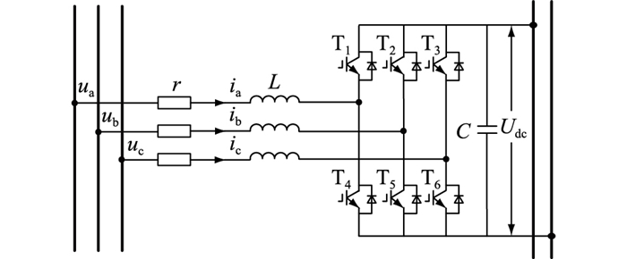
1 三相AC/DC换流器数学模型直流微电网典型结构包括光伏发电系统、直流负荷及储能系统。三相AC/DC换流器连接直流母线与大电网,可根据电网中的功率状况,即判断其工作在整流或逆变状态来控制微电网与大电网之间的潮流传递,保证微电网的可靠稳定运行,其拓扑结构见图 1。r为线路等效电阻;L为线路等效电感;C为直流侧稳压电容;Udc为直流母线电压;ua,ub,uc为交流侧相电压;ia,ib,ic为交流侧相电流。
|
图 1 三相AC/DC换流器拓扑结构 Fig. 1 Topological structure of three-phase AC/DC converter |
从图 1可得,三相静止坐标系下三相AC/DC换流器的数学模型为:
| $ \left\{\begin{array}{l} u_{\mathrm{a}}=L \frac{\mathrm{d} i_{\mathrm{a}}}{\mathrm{d} t}+r i_{\mathrm{a}}+u_{\text {cona }} \\ u_{\mathrm{b}}=L \frac{\mathrm{d} i_{\mathrm{b}}}{\mathrm{d} t}+r i_{\mathrm{b}}+u_{\mathrm{conb}} \\ u_{\mathrm{c}}=L \frac{\mathrm{d} i_{\mathrm{c}}}{\mathrm{d} t}+r i_{\mathrm{e}}+u_{\mathrm{conc}} \end{array}\right. $ | (1) |
式中:ucona,uconb,uconc为三相AC/DC换流器桥中点控制电压。
对式(1)进行Tabc-dq变换后,三相AC/DC换流器的数学模型为:
| $ \left\{\begin{array}{l} u_{d}=L \frac{\mathrm{d} i_{d}}{\mathrm{~d} t}-\omega L i_{q}+r i_{d}+u_{\text {con }d} \\ u_{q}=L \frac{\mathrm{d} i_{q}}{\mathrm{~d} t}+\omega L i_{d}+r i_{q}+u_{\text {con }q} \end{array}\right. $ | (2) |
式中:ud,uq为两相旋转坐标系下交流侧电压;id,iq为两相旋转坐标系下交流侧电流;ucond,uconq为两相旋转坐标系下三相AC/DC换流器桥中点控制电压。取三相AC/DC换流器交流侧电流为新的状态变量,则系统的状态方程整理为:
| $ \left\{\begin{array}{l} \dot{i}_{d}=\frac{u_{d}}{L}+\omega i_{q}-\frac{r i_{d}}{L}-\frac{u_{\text {cond }}}{L} \\ \dot{i}_{q}=\frac{u_{q}}{L}-\omega i_{d}-\frac{r i_{q}}{L}-\frac{u_{\text {con } q}}{L} \end{array}\right. $ | (3) |
由图 1和系统的数学模型可得,系统的瞬时有功表达式为:
| $ C \frac{\mathrm{d} U_{\mathrm{dc}}}{\mathrm{d} t} U_{\mathrm{dc}}+U_{\mathrm{dc}} I_{\mathrm{dc}}=\frac{3}{2}\left(u_{d} i_{d}+u_{q} i_{q}\right) $ | (4) |
式中:Idc为三相AC/DC换流器直流侧电流。
整理得:
| $ \dot{U}_{\mathrm{dc}}=3\left(u_{q} i_{q}+u_{d} i_{d}\right) /\left(2 C U_{\mathrm{dc}}\right)-I_{\mathrm{dc}} / C $ | (5) |
为便于分析,分别令y1=iq;y2=id;y3=Udc。设d、q轴电流环和电压环的总和扰动分别为:
| $ \left\{\begin{array}{l} d_{1}=-\omega i_{d}-r i_{q} / L-u_{\text {conq }} / L \\ d_{2}=\omega i_{q}-r i_{d} / L \\ d_{3}=-I_{\mathrm{dc}} / C \end{array}\right. $ | (6) |
| $ \left\{\begin{array}{l} b_{1}=b_{2}=1 / L \\ b_{3}=3 u_{d} /\left(2 C U_{\mathrm{dc}}\right) \end{array}\right. $ | (7) |
则非线性强耦合系统(3)和(5)可映射为一个未知线性系统:
| $ \left\{\begin{array}{l} \dot{y}_{1}=d_{1}+b_{1} u_{q} \\ \dot{y}_{2}=d_{2}+b_{2} u_{d} \\ \dot{y}_{3}=d_{3}+b_{3} i_{d} \end{array}\right. $ | (8) |
设直流侧电压参考值为Udc*,d轴电流期望指令为id*,q轴电流期望指令为iq*。由于三相AC/DC换流器采用iq*=0控制,因此,定义直流母线电压跟踪误差eu1、d轴电流跟踪误差ed1和q轴电流跟踪误差eq1及三者的积分分别为:
| $ \left\{\begin{array}{l} e_{\mathrm{u} 1}=U_{\mathrm{dc}}^{*}-y_{3} \\ e_{d 1}=i_{d}^{*}-y_{2} \\ e_{q 1}=-y_{1} \end{array}\right. $ | (9) |
| $ \left\{\begin{array}{l} e_{\mathrm{u} 0}=\int_{0}^{t} e_{\mathrm{u} 1} \mathrm{~d} \tau \\ e_{d 0}=\int_{0}^{t} e_{d 1} \mathrm{~d} \tau \\ e_{q 0}=\int_{0}^{t} e_{q 1} \mathrm{~d} \tau \end{array}\right. $ | (10) |
式中:τ为时间尺度。结合式(8),可建立一个在总和扰动d3,d2和d1反相激励下的受控误差系统:
| $ \left\{\begin{array}{l} \dot{e}_{\mathrm{ul}}=\dot{U}_{\mathrm{dc}}^{*}-d_{3}-b_{3} i_{d} \\ \dot{e}_{d 1}=\dot{i}_{d}^{*}-d_{2}-b_{2} u_{d} \\ \dot{e}_{q 1}=-d_{1}-b_{1} u_{q} \end{array}\right. $ | (11) |
根据文献[20]的控制理论思想,为了使控制误差eu1,ed1和eq1稳定趋于零点,定义电压环、d轴电流环和q轴电流环的ACPI控制器模型为:
| $ \left\{\begin{array}{l} i_{d}^{*}=\left(z_{\mathrm{u}}^{2} e_{\mathrm{u} 0}+2 z_{\mathrm{u}} e_{\mathrm{u} 1}\right) b_{3}^{-1} \\ u_{d}=\left(z_{d}^{2} e_{d 0}+2 z_{d} e_{d 1}\right) b_{2}^{-1} \\ u_{q}=\left(z_{q}^{2} e_{q 0}+2 z_{q} e_{q 1}\right) b_{1}^{-1} \end{array}\right. $ | (12) |
式中:zu,zd,zq分别为电压环、d轴电流环和q轴电流环ACPI控制器的速度因子,zu>0,zd>0,zq>0。
由电压环、d轴电流环、q轴电流环组成的ACPI控制系统结构如图 2所示。图中,ud*,uq*为两相旋转坐标系下交流侧电压期望指令; uabc为交流侧三相电压;SVPWM为空间矢量脉宽调制。

|
图 2 ACPI控制系统结构 Fig. 2 Structure of ACPI control system |
为了分析分别由电压环、d轴电流环和q轴电流环ACPI组成的子闭环控制系统(12)的鲁棒稳定性和抗总和扰动鲁棒性,文中对电压环ACPI闭环控制系统的稳定性进行分析。由于篇幅有限,d轴电流环ACPI闭环控制系统和q轴电流环ACPI闭环控制系统的稳定性分析参照电压环ACPI闭环控制系统,文中不再赘述。
将式(10)代入式(11),进行拉式变换后可得受控误差系统的传递函数为[20]:
| $H_{\mathrm{u}}(s)=s /\left(s+z_{\mathrm{u}}\right)^{2} $ | (13) |
由式(13)可知,当zu≥0时,Hu(s) 有且仅有唯一的二重极点s=-zu在复频域左半平面的实轴上。由复频域分析理论可知,系统(13)是大范围稳定的。又因为zu与电压环的动态模型无关,因而系统(13)是大范围鲁棒稳定的。
当|d3|≤ε3,
| $ \left|\hat{d}_{3}\right|=\left|\dot{U}_{\mathrm{dc}}^{*}-d_{3}\right| \leqslant\left|\dot{U}_{\mathrm{dc}}^{*}\right|+\left|d_{3}\right| \leqslant \varepsilon_{\mathrm{u}}+\varepsilon_{3} $ | (14) |
由式(13)可得系统单位冲激响应为:
| $ h_{\mathrm{u}}(t)=\left(1-z_{\mathrm{u}} t\right) \mathrm{e}^{-z_{\mathrm{u}} t} $ | (15) |
当zu≥0时,
| $e_{\mathrm{u} 1}(t)=h_{\mathrm{u}}(t) * \hat{d}_{3}(t)=\int_{0}^{t} h_{\mathrm{u}}(\tau) \hat{d}_{3}(t-\tau) \mathrm{d} \tau $ | (16) |
式中:*为卷积积分运算符。
考虑到
| $ \begin{gathered} \left|e_{\mathrm{ul}}(t)\right|=\left|\int_{0}^{t} h_{\mathrm{u}}(\tau) \hat{d}_{3}(t-\tau) \mathrm{d} \tau\right| \leqslant \\ \int_{0}^{t}\left|h_{\mathrm{u}}(\tau)\right|\left|\hat{d}_{3}(t-\tau)\right| \mathrm{d} \tau \leqslant\left(\varepsilon_{\mathrm{u}}+\varepsilon_{3}\right) \int_{0}^{t}\left|h_{\mathrm{u}}(\tau)\right| \mathrm{d} \tau \end{gathered} $ | (17) |
因而有:
| $\left|e_{\mathrm{u} 1}(\infty)\right| \leqslant\left(\varepsilon_{\mathrm{u}}+\varepsilon_{3}\right) \int_{0}^{\infty}\left|h_{\mathrm{u}}(\tau)\right| \mathrm{d} \tau $ | (18) |
由于
| $ \int_{0}^{\infty}\left|h_{\mathrm{u}}(\tau)\right| \mathrm{d} \tau=\int_{0}^{1 / z_{\mathrm{u}}} h_{\mathrm{u}}(\tau) \mathrm{d} \tau+\int_{1 / z_{\mathrm{u}}}^{\infty} h_{\mathrm{u}}(\tau) \mathrm{d} \tau $ | (19) |
因而有:
| $ \int_{0}^{1 / z_{\mathrm{u}}} h_{\mathrm{u}}(\tau) \mathrm{d} \tau=-\int_{1 / z_{\mathrm{u}}}^{\infty} h_{\mathrm{u}}(\tau) \mathrm{d} \tau=\int_{1 / z_{\mathrm{u}}}^{\infty}\left|h_{\mathrm{u}}(\tau)\right| \mathrm{d} \tau $ | (20) |
将式(20)代入式(19)可得:
| $ \int_{0}^{\infty}\left|h_{\mathrm{u}}(\tau)\right| \mathrm{d} \tau=2 \int_{0}^{1 / z_{\mathrm{u}}} h_{\mathrm{u}}(\tau) \mathrm{d} \tau=\frac{2}{\mathrm{e} z_{\mathrm{u}}} <\frac{1}{z_{\mathrm{u}}} $ | (21) |
其中,e≈2.71为自然常数。将式(21)代入式(18)可得:
| $ \left|e_{\mathrm{u} 1}(\infty)\right| \leqslant \frac{\varepsilon_{\mathrm{u}}+\varepsilon_{3}}{z_{\mathrm{u}}} $ | (22) |
式(22)表明,稳态误差随zu的增加而变小,当
由2.2节可知,当zu≥0,zd≥0,zq≥0时,电压环ACPI控制系统、d轴电流环ACPI控制系统以及q轴电流环ACPI控制系统都是大范围鲁棒稳定的,表明速度因子zu,zd,zq都是大范围鲁棒稳定的,且具有很大的镇定裕度。
为实现对被控对象的有效控制,须保证ACPI的速度因子大于被控对象动态变化速度,而被控对象的动态变化速度又由被控对象的时间尺度τ决定。τ越大,被控对象的变化速度(1/τ)越慢,因此, 可设ACPI的最小速度因子分别为:
| $ \left\{\begin{array}{l} z_{\mathrm{um}}=\alpha_{\mathrm{u}} / \tau \\ z_{d \mathrm{~m}}=\alpha_{d} / \tau \\ z_{q \mathrm{~m}}=\alpha_{q} / \tau \end{array}\right. $ | (23) |
式中:αu为电压环控制参数;αd为d轴电流环控制器参数;αq为q轴控制器参数。1<αu≤10,1<αd≤10,1<αq≤10。
对于文中被控系统而言,时间尺度τ难以获取,因此,由式(23)来整定最小速度因子zum,zdm,zqm会遇到理论或技术上的困难。
文中利用被控系统由动态过渡到稳态的时间T0来估计τ。设T0=5τ,则式(23)可表示为:
| $ \left\{\begin{array}{l} z_{\mathrm{um}}=5 \alpha_{\mathrm{u}} / T_{0} \\ z_{d \mathrm{~m}}=5 \alpha_{d} / T_{0} \\ z_{q \mathrm{~m}}=5 \alpha_{q} / T_{0} \end{array}\right. $ | (24) |
显然,ACPI控制器的最小速度因子zum,zdm,zqm通过被控对象的稳态过渡时间T0来整定,不仅可以解决传统PI控制中增益整定的难题,还为未知系统的精确控制提供了全新思路。
最小速度因子中控制参数αu,αd,αq的设定会直接影响控制器的控制效果。为使系统响应速度更快,一般要求控制参数越大越好,但是过大可能会出现超调或振荡现象,过小又会造成控制力不足。因此,为兼顾系统动态品质与稳态性能,应使用自适应速度因子。而文献[20]提出的随时间变化的自适应速度因子无法对突变扰动及时调整,为使速度因子拥有更快的反应速度,文中设计了如下基于误差的改进自适应速度因子:
| $ \left\{\begin{array}{l} z_{\mathrm{u}}=z_{\mathrm{um}} \mathrm{e}^{-\beta_{\mathrm{u}}\left|e_{\mathrm{u} 1}\right|} \\ z_{d}=z_{d \mathrm{~m}} \mathrm{e}^{-\beta_{d}\left|e_{d 1}\right|} \\ z_{q}=z_{q \mathrm{~m}} \mathrm{e}^{-\beta_{q}\left|e_{q 1}\right|} \end{array}\right. $ | (25) |
式中:βu,βd,βq为绝对误差的增益系数。βu=1+αu;βd=1+αd;βq=1+αq。
控制参数越大,速度因子则越大,系统的抗总和扰动性能越强。当系统误差出现变化时,该速度因子能及时反应,极大增强了系统的抗总和扰动鲁棒性。而当系统达到稳态时,自适应速度因子达到最大值,结合式(8)、式(22)即可得出在改进ACPI控制下,直流母线电压的理论控制结果为:
| $ \left|e_{\mathrm{u} 1}(\infty)\right| \leqslant \frac{3 u_{d}}{2 z_{\mathrm{u}} C U_{\mathrm{dc}}} $ | (26) |
因此在系统处于稳态时,改进自适应速度因子可以极大增强ACPI控制力度,实现直流母线电压的高精度控制。
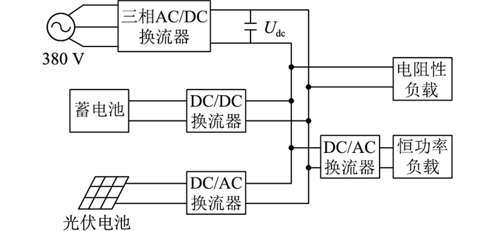
3 不同工况仿真分析为验证文中控制方法的有效性,在Matlab/Simulink环境中搭建了如图 3所示的直流微电网,并分别针对并网启动、负荷意外切除、参数摄动和光照扰动工况进行仿真研究。直流微电网的仿真系统参数如表 1所示。
|
图 3 直流微电网拓扑结构 Fig. 3 Topology structure of DC microgrid |
|
|
表 1 仿真系统参数 Table 1 Simulation system parameters |
文中将详细介绍改进ACPI控制方法相比文献[23]的PI控制方法和文献[20]的传统ACPI控制法在启动特性、负载意外切除、参数摄动、光伏并网等不同工况下的具体优势。
3.1 并网启动仿真分析改进ACPI控制方法与PI控制方法和传统ACPI控制方法在并网启动工况下母线电压控制效果对比如图 4所示。由图 4可知,当直流微电网并网启动时,PI控制方法的超调现象明显,加载后母线电压不稳定,存在较长的过渡时间,不利于微电网稳定运行。而改进ACPI控制方法下的母线电压不仅无超调现象,而且与传统ACPI控制方法相比,母线电压仅在0.05 s内便上升至设定值,启动速度更快,减少了启动过程中系统对电网的冲击,表明了改进ACPI控制方法具有良好的启动特性。

|
图 4 并网启动工况下母线电压控制效果 Fig. 4 The effect of bus voltage control under grid-connected start-up conditions |
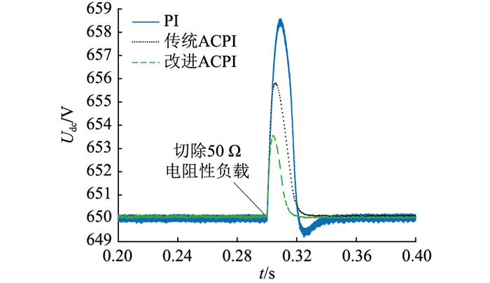
0.3 s时,电阻性负载意外切除,3种控制方法的仿真结果对比见图 5。由图 5可知,在系统稳态时,改进ACPI控制方法的控制精度远高于PI控制方法。在负载意外切除的工况下,PI控制方法大约经历0.04 s达到稳定,且存在超调现象。传统ACPI控制方法虽然无超调现象,但直流母线电压响应速度仍较慢。而改进ACPI控制方法在扰动下仍能保持母线电压稳定,虽然负载意外切除瞬间母线电压出现上升,但能在0.02 s内恢复到设定值。相比之下,改进ACPI控制方法具有更强的抗扰鲁棒性。
|
图 5 负载意外切除工况下母线电压控制效果 Fig. 5 The effect of bus voltage control under accidental load removal conditions |
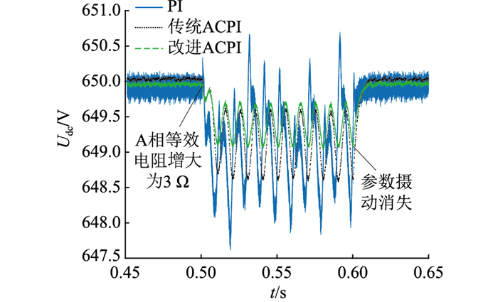
0.5 s时,三相AC/DC变换器交流侧发生参数摄动,A相等效电阻增大至3 Ω,在0.6 s时恢复至0.1 Ω,仿真结果如图 6所示。从图 6可以看出,在参数摄动的工况下,与PI控制方法和传统ACPI控制方法相比,采用改进ACPI方法控制的母线电压波动幅度更小。当参数摄动消失时,母线电压迅速恢复至设定值,保证了系统的稳定运行。
|
图 6 参数摄动工况下母线电压控制效果 Fig. 6 The effect of bus voltage control under parameter perturbation conditions |
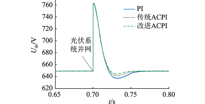
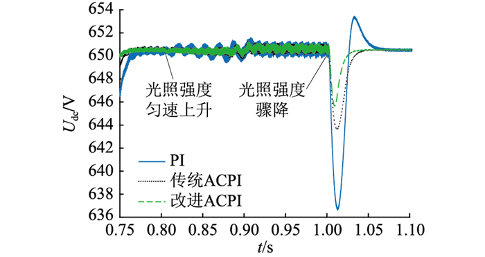
0.7 s时,光伏系统接入微电网,0.8~0.9 s时,光照强度由500 W/m2匀速上升至1 000 W/m2,在1 s时跌落至100 W/m2。仿真结果见图 7、图 8。
|
图 7 光伏并网工况下母线电压控制效果 Fig. 7 The effect of bus voltage control under photovoltaic grid-connected conditions |
|
图 8 光照扰动工况下母线电压控制效果 Fig. 8 The effect of bus voltage control under illumination disturbance conditions |
仿真结果表明,光伏系统并网时,改进ACPI控制方法下的母线电压在0.05 s内即可恢复至设定值,且超调量小于PI控制方法和传统ACPI控制方法,更有利于光伏系统并网。在光照渐变的情况下,PI控制方法控制下的直流母线电压出现了振荡现象。而改进ACPI控制方法的三相AC/DC换流器的直流母线电压仍保持稳定,系统持续抗扰能力强。在光照突变的情况下,与PI控制方法和传统ACPI控制方法相比,改进ACPI控制方法的直流母线电压响应时间更短,效果更好,且基本无超调现象。
4 结语针对直流微电网中三相AC/DC换流器在内外扰动下出现母线电压波动的问题,文中提出了一种基于ACPI控制理论的母线电压控制方法。理论分析了ACPI控制系统的大范围鲁棒稳定性和抗总和扰动鲁棒性,合理推导出了在ACPI控制器控制下的速度因子与系统稳态误差之间的关系,对提高稳态精度具有重要指导意义。此外,文中还设计了一种新型的基于系统误差的改进自适应速度因子,有效提高了系统的动态品质和稳态性能。仿真结果表明,与传统PI控制方法相比,改进ACPI控制方法不仅控制结果更佳,而且控制系统结构更为简单,每个ACPI控制器只涉及一个速度因子。文中的改进ACPI控制方法计算量小、实时性好,更便于实际应用,在微电网领域具有广泛的应用价值。
| [1] |
桑博, 张涛, 刘亚杰, 等. 多微电网能量管理系统研究综述[J]. 中国电机工程学报, 2020, 40(10): 3077-3093. SANG Bo, ZHANG Tao, LIU Yajie, et al. Energy management system research of multi-microgrid: a review[J]. Proceedings of the CSEE, 2020, 40(10): 3077-3093. (  0) 0) |
| [2] |
刘畅, 卓建坤, 赵东明, 等. 利用储能系统实现可再生能源微电网灵活安全运行的研究综述[J]. 中国电机工程学报, 2020, 40(1): 1-18, 369. LIU Chang, ZHUO Jiankun, ZHAO Dongming, et al. A review on the utilization of energy storage system for the flexible and safe operation of renewable energy microgrids[J]. Proceedings of the CSEE, 2020, 40(1): 1-18, 369. (  0) 0) |
| [3] |
SEKIZAKI S, MATSUO K, NAKAMURA Y, et al. Stabilization of microgrid with multiple inverters[J]. IFAC-PapersOnLine, 2018, 51(28): 149-154. DOI:10.1016/j.ifacol.2018.11.693 (  0) 0) |
| [4] |
石榴, 廖凯, 杨健维, 等. 计及系统延迟的直流微电网经济运行控制策略[J]. 电网技术, 2022, 46(1): 138-145. SHI Liu, LIAO Kai, YANG Jianwei, et al. Distributed economic optimal operation control strategy for islanded DC microgrids considering system delay[J]. Power System Technology, 2022, 46(1): 138-145. (  0) 0) |
| [5] |
张伟亮, 张辉, 支娜, 等. 考虑网络损耗的基于模型预测直流微电网群能量优化策略[J]. 电力系统自动化, 2021, 45(13): 49-56. ZHANG Weiliang, ZHANG Hui, ZHI Na, et al. Model prediction based energy optimization strategy for DC microgrid groups considering network loss[J]. Automation of Electric Power Systems, 2021, 45(13): 49-56. (  0) 0) |
| [6] |
阮绵晖, 郑建平, 刘尧, 等. 离网直流微网群混合储能容量优化配置方法[J]. 电力工程技术, 2021, 40(3): 99-105. RUAN Mianhui, ZHENG Jianping, LIU Yao, et al. Optimization configuration method for hybrid energy storage capacity of independent DC microgrid cluster[J]. Electric Power Engineering Technology, 2021, 40(3): 99-105. (  0) 0) |
| [7] |
CHOI T S, KO J H, OH J S, et al. Operation method of DC micro grid using power control[J]. Journal of International Council on Electrical Engineering, 2019, 9(1): 15-23. (  0) 0) |
| [8] |
刘子文, 苗世洪, 范志华, 等. 基于自适应下垂特性的孤立直流微电网功率精确分配与电压无偏差控制策略[J]. 电工技术学报, 2019, 34(4): 795-806. LIU Ziwen, MIAO Shihong, FAN Zhihua, et al. Accurate power allocation and zero steady-state error voltage control of the islanding DC microgird based on adaptive droop characteristics[J]. Transactions of China Electrotechnical Society, 2019, 34(4): 795-806. (  0) 0) |
| [9] |
孟明, 贺海博, 王志鹏, 等. 直流微网低电压穿越控制策略研究[J]. 电测与仪表, 2017, 54(2): 31-37. MENG Ming, HE Haibo, WANG Zhipeng, et al. LVRT control strategy for DC micro-grid[J]. Electrical Measurement & Instrumentation, 2017, 54(2): 31-37. (  0) 0) |
| [10] |
HATAHET W, MAREI M I, MOKHTAR M. Adaptive controllers for grid-connected DC microgrids[J]. International Journal of Electrical Power & Energy Systems, 2021, 130: 106917. (  0) 0) |
| [11] |
刘畅. 基于矢量调制的三相三端口DC-AC变流器功率流控制方法研究[D]. 杭州: 浙江大学, 2021. LIU Chang. Research on power flow control strategy of three-port-three-phase DC-AC converter based on space vector modulation[D]. Hangzhou: Zhejiang University, 2021. (  0) 0) |
| [12] |
刘子文, 苗世洪, 范志华, 等. 孤立交直流混合微电网双向AC/DC换流器功率控制与电压波动抑制策略[J]. 中国电机工程学报, 2019, 39(21): 6225-6238. LIU Ziwen, MIAO Shihong, FAN Zhihua, et al. Power control and voltage fluctuation suppression strategy of the bidirectional AC/DC converter in the islanding hybrid microgrid[J]. Proceedings of the CSEE, 2019, 39(21): 6225-6238. (  0) 0) |
| [13] |
郭仕林, 苏建徽, 陈学健, 等. 基于双辅助网络的宽软开关范围高效高频链DC-AC变换器[J]. 中国电机工程学报, 2017, 37(18): 5377-5388, 5537. GUO Shilin, SU Jianhui, CHEN Xuejian, et al. Wide-range soft-switching high-efficiency high-frequency-link DC-AC converter based on dual auxiliary network[J]. Proceedings of the CSEE, 2017, 37(18): 5377-5388, 5537. (  0) 0) |
| [14] |
李霞林, 郭力, 冯一彬, 等. 基于非线性干扰观测器的直流微电网母线电压控制[J]. 中国电机工程学报, 2016, 36(2): 350-359. LI Xialin, GUO Li, FENG Yibin, et al. A nonlinear disturbance observer based DC bus voltage control for a DC microgrid[J]. Proceedings of the CSEE, 2016, 36(2): 350-359. (  0) 0) |
| [15] |
梁海峰, 边吉, 丁锦睿, 等. 基于滑模控制的孤岛直流微电网控制策略研究[J]. 华北电力大学学报(自然科学版), 2021, 48(1): 15-23, 41. LIANG Haifeng, BIAN Ji, DING Jinrui, et al. Research on control strategy of isolated DC microgrid based on sliding mode control[J]. Journal of North China Electric Power University (Natural Science Edition), 2021, 48(1): 15-23, 41. (  0) 0) |
| [16] |
吴博宁, 高志强, 周雪松, 等. 基于超螺旋二阶滑模理论的直流微电网母线电压控制[J/OL]. 电测与仪表: 1-7[2022-01-12]. http://kns.cnki.net/kcms/detail/23.1202.TH.20210524.1008.002.html. WU Boning, GAO Zhiqiang, ZHOU Xuesong, et al. Bus voltage control of DC micro-grid based on super-helix second-order sliding mode theory[J/OL]. Electrical Measurement and Instrumentation: 1-7[2022-01-12]. http://kns.cnki.net/kcms/detail/23.1202.TH.20210524.1008.002.html. (  0) 0) |
| [17] |
韩永强, 徐明忻, 孙碣, 等. 基于VGLESO和滑模理论的直流配电网母线电压控制策略[J]. 南方电网技术, 2021, 15(1): 33-40. HAN Yongqiang, XU Mingxin, SUN Jie, et al. Bus voltage control strategy of DC distribution network based on VGLESO and sliding mode theory[J]. Southern Power System Technology, 2021, 15(1): 33-40. (  0) 0) |
| [18] |
康忠健, 陈醒, 崔朝丽, 等. 基于ESO与终端滑模控制的直流配电网母线电压控制[J]. 中国电机工程学报, 2018, 38(11): 3235-3243. KANG Zhongjian, CHEN Xing, CUI Zhaoli, et al. Bus voltage control method of DC distribution network based on ESO and terminal sliding mode control[J]. Proceedings of the CSEE, 2018, 38(11): 3235-3243. (  0) 0) |
| [19] |
高明明, 赵晋斌, 屈克庆, 等. 基于RBF神经网络的直流微电网均流控制策略[J]. 可再生能源, 2020, 38(3): 396-403. GAO Mingming, ZHAO Jinbin, QU Keqing, et al. Current sharing control strategy for DC microgrid based on RBF neural net- work[J]. Renewable Energy Resources, 2020, 38(3): 396-403. (  0) 0) |
| [20] |
曾喆昭, 刘文珏. 自耦PID控制器[J]. 自动化学报, 2021, 47(2): 404-422. ZENG Zhezhao, LIU Wenjue. Self-coupling PID controllers[J]. Acta Automatica Sinica, 2021, 47(2): 404-422. (  0) 0) |
| [21] |
曾喆昭, 刘文珏. 一阶时滞系统的智慧PI控制[J]. 控制理论与应用, 2019, 36(8): 1322-1328. ZENG Zhezhao, LIU Wenjue. Wisdom PI control for first-order systems with time-delay[J]. Control Theory & Applications, 2019, 36(8): 1322-1328. (  0) 0) |
| [22] |
曾喆昭, 陈泽宇. 论PID与自耦PID控制理论方法[J]. 控制理论与应用, 2020, 37(12): 2654-2662. ZENG Zhezhao, CHEN Zeyu. On control theory of PID and auto-coupling PID[J]. Control Theory & Applications, 2020, 37(12): 2654-2662. (  0) 0) |
| [23] |
王晓辉. 微电网运行仿真技术[M]. 北京: 中国建筑工业出版社, 2018. WANG Xiaohui. Operation simulation technology of microgrid[M]. Beijing: China Architecture & Building Press, 2018. (  0) 0) |
 2022, Vol. 41


 周蔚(1998), 男, 硕士在读, 研究方向为电能质量、电能路由器等(E-mail: